PSTN Line Connection (DualCom ALONE on line)
Your Telecom Service Provider should be asked to supply and fit an analogue
line and an NTP with terminals near the alarm system. The alarm installer
should then follow steps 1 & 2 below. See Fig 15 & 16.
Series Connection (DualCom & OTHER EQUIPMENT on line)
Your Telecom Service Provider should be asked to supply and fit an analogue
line and an NTP with terminals near the alarm system. The alarm installer
should then follow steps 1 to 3 below. See Fig 15 & 16.
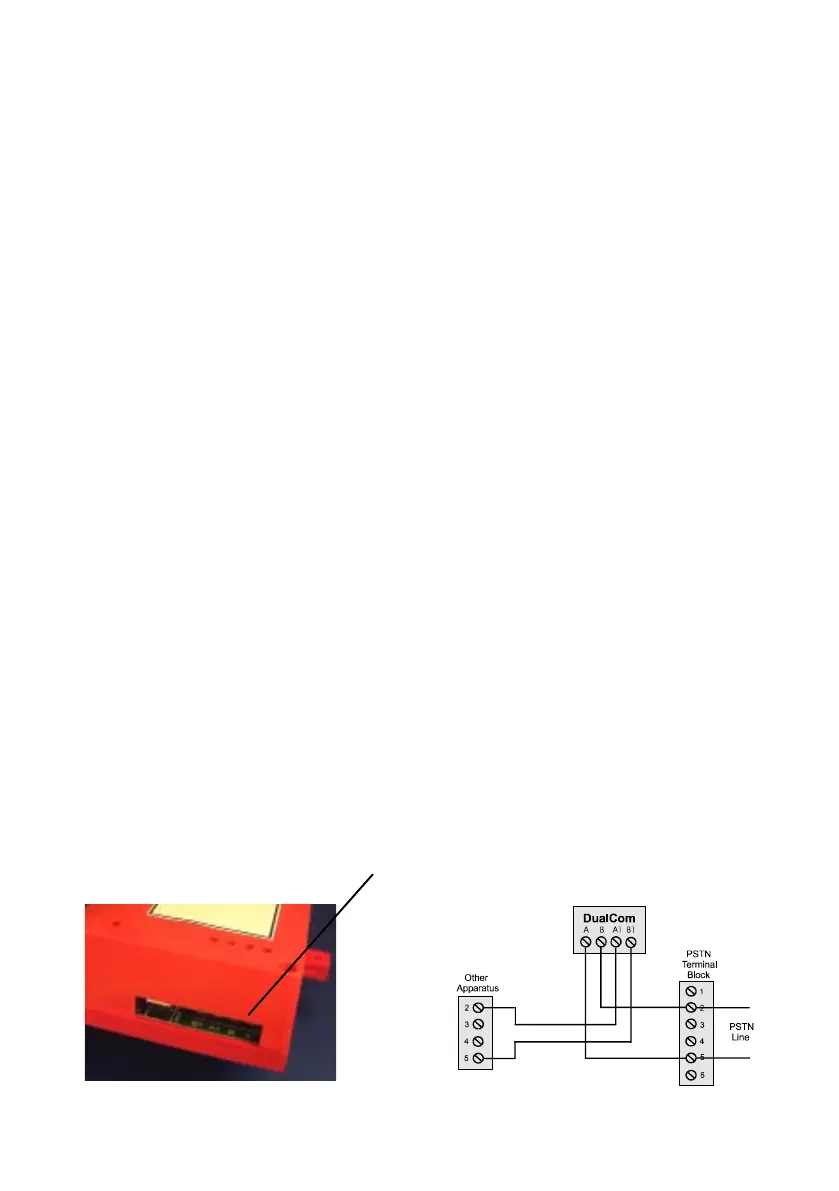
1. Connect a PSTN cable to the A & B terminals. Screwdriver access is pro-
vided in the DualCom so that the lid need not be removed. See Fig 1.
2. Connect the other end of the cable to the Terminal Block connections for the
incoming telephone line, marked A & B, or 2 & 5.
3. If the PSTN line used by DualCom is shared with other customer apparatus
(e.g. telephone, fax or answer machine) connect the DualCom’s terminals
marked A1 and B1 to a new PSTN Master Socket. The customer may then
plug their phone, fax etc, into that socket. See Fig 16.
A PSTN Master Socket type LJU2/4A is suitable and has screw terminals
for connection. These can be obtained from many electrical distributors in-
cluding:
CPC Part Number: TE 05285
Farnell Part Number: 916-638 or 101-3290
Maplin Part Number: FT48C
Rapid Part Number: 24-0116
RS Part Number: 472-534
35
Fig 15
Fig 16
PSTN Telephone
Connections