Yellow Radio Service LED. See Fig 31 below
47
DELsutatSwolleY snoitacidnIhtaPoidaR oddluohsuoytahW
ffO
eludomoidarmoClauDotrewopoN .ylppuskcehC
dilosnO
noitartsigeRteser/pu-rewoP etunim1tiaW
noknilb+ffO
.sces2yreveecno
.detcetednoitatSesaBoidaR
.elbaliavaecivresMSG
.ecivresrofydaeR.no-dekcoL
tonyam/yamecivresSRPG:etoN
elbaliavaeb
Table 13
APPENDIX 1
LED Indications
Status LEDs
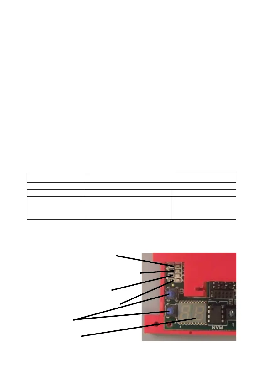
There are 4 Status LEDs next to the A & B buttons. See Fig 31 below.
These LEDs indicate Call Progress, Faults and other activity on the Radio, LAN
and PSTN paths. See Tables 14 to 21.
The Radio Service LED indicates status of the GSM/GPRS radio module. See
Table 13 below.
The A & B buttons and the the 7-segment display are used for setup and meas-
urement functions. See Tables 30 to 34.
In addition, the 7-segment display will also show error codes where errors exist
in communication or operation. See Table 36.
Yellow Radio Status LED (GSM & GPRS)
Green Wired Status LED (LAN/IP)
Red Wired Status LED (PSTN)
‘7 Segment’ display
A and B Buttons
Yellow Radio Service LED (SVC)
Fig 31