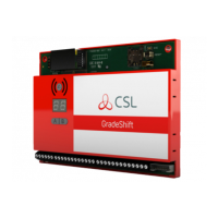
APPENDIX 1
A & B buttons & the 7 Segment Display
The A & B buttons are used for setup and measurement functions.
When no buttons are pressed for a 1 minute period, the display will automati-
cally return to the received radio signal strength (FSSI) display.
The DualCom 7-segment display has 3 distinct modes.
1. Power up - Reset Mode
The A & B buttons can clear some NVM settings. See Table 34.
The display first shows all segments ‘on’ and all LEDs ‘on’ for 1 second.
Then, the software version number as two separate 1 or 2 digit numbers.
Then, the EN50136 Grade,
Then, the initialisation states of the Radio, LAN & PSTN paths.
Press A button then Reset or Power-up the DualCom. This will clear the
Plug-on Adapter memory and clear any pending calls stored in the NVM.
The button should be held down until the Dualcom ‘beep-beeps’ to acknowl-
edge this function. This also resets the polling delay to 45mins.
2. Communication Mode
The A & B buttons are disabled during communication. See Table 33.
The display shows large C for Wired comms. and small c for Radio comms.
Call progress is shown by C1, C2, C3 and ‘A’ to indicate a successful call.
.
The appropriate GSM, PSTN or LAN LEDs will light to indicate activity and
call progress.
3. Normal Mode
This ‘normal’ mode means that the DualCom is not in Power-up - Reset
mode and not in Communication mode. See Tables 30, 31,32 and 36.
The A & B buttons can select display options and Program the NVM.
When the A & B buttons are not pressed for 1 minute, the display will return
to the received radio signal strength (FSSI) value (00-99).
Any Error Code will display for 1 minute before reverting to the FSSI value.
51

 Loading...