65
APPENDIX 3
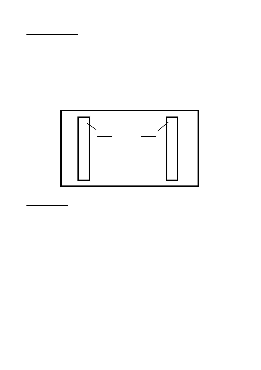
Plug-on Footprint
‘Plug-on’ pins are mounted on some Control Panels for connection to commu-
nication devices. The pins are fitted on a plastic spacer, 0.156 inches (3.96mm)
pin centre to centre. There are two rows of 8 pins spaced apart by 4.25 inches
(108mm) pin centre to centre.
The view below is looking at the pins on a Control Panel, onto which the CS2325
Plug-on Adapter plugs. Note that some equipments label the pins 9-16 as ‘1-8’
as well as the pins that are 1 - 8.
Pin Allocation
1 Input to DualCom Input 1 Fire
2 Input to DualCom Input 2 P.A.
3 Input to DualCom Input 3 Burglar
4 Input to DualCom Input 4 Open/Close
5 Input to DualCom Input 5
6 Output from DualCom Tell Back (comms successful)
7 Output from DualCom Communications Fail
8 Input to DualCom (unused)
9 Input to DualCom +12 volts (from Control Panel)
10 Input to DualCom 0v (from Control Panel)
11 Input to DualCom ATS Test input
12 Input to DualCom +5v (from Control Panel)
13 Input to DualCom Input 6
14 Input to DualCom Input 7
15 Output from DualCom PSTN Line Fail
16 Output from DualCom Input 8 (not used on older panels)
1o o 9
2 o o 10
3 o o 11
4 o o 12
5 o o 13
6 o o 14
7 o o 15
8 o o 16
Pin 1 Pin 1