APPENDIX 2
Input Connections
There are 8 input terminals on DualCom (12 with the CS2351 and CS2355
Expanders).
When DualCom is triggered, the voltages on the input terminals are 0 volts
changing to a positive voltage, (normally +5 volts to +30 volts), or they may be
a positive voltage changing to 0 volts. This is called ‘positive applied’ or ‘positive
removed’ triggering.
The Inputs may be programmed to send an alarm call when a positive voltage is
applied to an input or when a positive voltage is removed. See ‘Input Self
Learning’ on page 61.
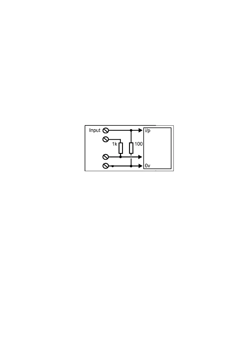
The figure above shows the internal connections of the DualCom inputs.
The voltage supply from the Control Panel or Power Supply is connected to the
+9-30v & 0v terminals.
Each of the input terminals on DualCom (and expander boards) is connected to
0 volts by a resistor. Therefore, by leaving an input terminal unconnected this
will ensure that the input remains connected to 0 volts.
Note: The ‘+’ terminal next to the 8 input terminals is a voltage output to aid
input triggering only. This terminal is NOT the supply connector. See Fig 2
and above.
Examples of input triggering connections are shown below.
DualCom internal connections
61
0v
+
DualCom
Circuits
K
+9-30v