INTRODUCTION MICRO-TEMP
®
LT, Model 749
OPERATION AND TECHNICAL MANUAL
Page 12 of 75
1-3. PHYSICAL DESCRIPTION OF THE MICRO-TEMP
®
LT UNIT
See Section 7 for specifications and certifications of the MICRO-TEMP
®
LT.
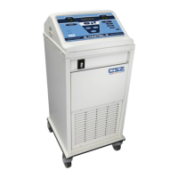
1-3.1. EXTERNAL FEATURES - FRONT VIEW
The external features in Figure 1-1 of the MICRO-TEMP
®
LT unit are described as follows:
A. The membrane on the front of the unit allows the user to change the temperature of
the water flowing through the thermal pad. It displays error messages and sounds an
audible indicator if there is a problem with the device. Refer to Section 1-3.3 for
descriptions of controls on the membrane. Refer to Section 3-5 for the list of status
displays and indicator messages.
B. The air vents, on both the top and bottom of the unit, provide air circulation for the
control board.
C. The built in handle permits the operator to grip and pick up the unit when moving it.
D. The sight window allows the operator to visually see how much water is in the
reservoir.
E. The permanently attached hose connects the unit and the thermal pad.
F. The four rubber suction cups on the bottom of the unit help to prevent the unit from
tipping.
G. The coupling attached to the end of the twin black tubing allows a quick disconnect
for the heat therapy pad.
H. The skirt is used to help prevent leaks from the reservoir