INTRODUCTION MICRO-TEMP
®
LT, Model 749
OPERATION AND TECHNICAL MANUAL
Page 16 of 75
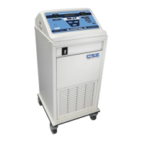
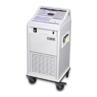
1-3.3. EXTERNAL FEATURES – MEMBRANE CONTROL PANEL
The external features in Figure (1-3) and Figure (1-4) of the MICRO-TEMP
®
LT unit are described
as follows:
A. The digital temperature display shows the actual temperature of the circulating water
and the set point temperature when the “SET” button is depressed. It also displays
indicator messages when a problem occurs, alerting the operator to make a change.
Refer to Section (3-5) for a list of possible display messages and indicators.
B. The “Low Water” symbol indicates when the unit is low on water by illuminating the
yellow LED to the left of the symbol. Refer to Section (3-5), Step (B) for Low Water
indicator.
C. The “Power Fail” symbol indicates when power has been interrupted by flashing the red
LED to the left of the symbol and sounding an audible indicator. Refer to Section (3-
5), Step (B) for Power Failure.
D. The “Caution” symbol indicates when the water temperature is >1°C (2°F) over the set
point temperature, the water has reached the high limit temperature of 44°C (111° F),
the tilt of the unit is beyond approximately 20˚ in any direction, or when there is a fault
within the unit by flashing/illuminating the red LED to the left of the symbol and
sounding an audible indicator. Refer to Section (3-5), Step (B).
E. The Increment button is used to increase the set point temperature when needed.
F. The “SET” temperature button is used to position the set point temperature.
G. The Decrement button is used to decrease the set point temperature when needed.
H. The “°C” button allows the operator to select Celsius as the measurement scale by
which the unit functions (100V and 115V only).
I. The “°F” button allows the operator to select Fahrenheit as the measurement scale by
which the unit functions (100V and 115V only).