INTRODUCTION MICRO-TEMP
®
LT, Model 749
OPERATION AND TECHNICAL MANUAL
Page 14 of 75
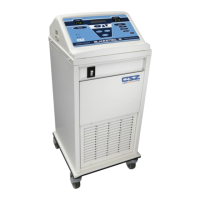
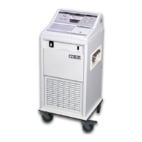
1-3.2. EXTERNAL FEATURES - REAR VIEW
The external features in Figure (1-2) of the MICRO-TEMP
®
LT unit are described as follows:
A. The power switch is a beveled rocker switch labeled “I” for ON and “O” for OFF.
B. The fuse housing holds replaceable fuses that are integrated in the switch assembly to
protect against overload conditions.
C. The main power connection is where the detachable power cord connects.
D. The detachable power cord with a hospital grade plug should only be inserted into a
properly grounded receptacle. Electrical specifications are described in Section (7).
E. The water fill opening, secured with a reservoir cap, is where the operator pours
distilled water into the unit to fill the reservoir.
F. The specification label outlines the MICRO-TEMP
®
LT unit's electrical requirements.
The condensed operating instructions found on the 115V allow the operator to see the
instructions and appropriately use the unit. The 230V contains symbols to describe
how to appropriately use the unit. The specification label also includes the unit serial
number and model number.
G. The recessed bottom is used to secure and store the permanently attached hose
and/or the power cord by wrapping the hose and/or cord around the unit when it is not
in use.
H. The equipment grounding terminal is used to perform the ground continuity test.
I. The skirt used for preventing leaks from the reservoir