FIELD REPAIR/SERVICE MICRO-TEMP
®
LT, Model 749
OPERATION AND TECHNICAL MANUAL
Page 45 of 75
5-2.3. DISCONNECTING THE CABLES FROM THE CONTROL BOARD
A. Separate the front enclosure from the rear enclosure. Refer to Section (5-2.1).
NOTE: DO NOT BEND ANY OF THE TERMINALS.
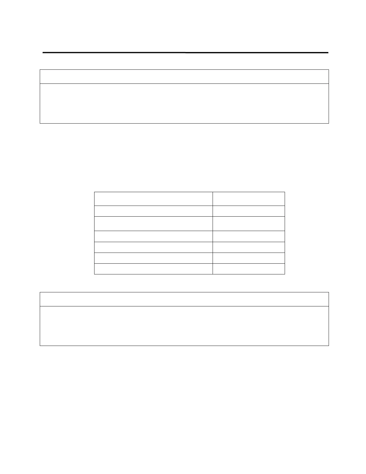
B. Locate the following connectors on the control board and disconnect them by
pinching the sides to disengage the connector lock, as required:
Blue 7-position membrane ribbon cable
connector
White 2-position water level connector
White 4-position temp sensor connector
White 3-position alarm enable connector
Red 6-position power connector
5-2.4. DISCONNECTING THE CABLES FROM THE DISPLAY BOARD
A. Remove cables from control board. Refer to Section (5-2.3).
B. Remove the seven 6-32” screws that secure the control board and remove board.
C. Using 7 mm nut driver, remove metal and plastic nuts that secure the display board.
D. Remove ground wire on display board.
E. Pull out display board.
Always unplug the unit before accessing internal components during service. Failure to
unplug the unit could result in electric shock.
Working with electronic boards, plugs, and cables requires delicate handling. Proper
Electrostatic Discharge (ESD) procedures should be followed during replacement of any
electronic board. Failure to do so may result in damage to the board.