FIELD REPAIR/SERVICE MICRO-TEMP
®
LT, Model 749
OPERATION AND TECHNICAL MANUAL
Page 32 of 75
PREVENTIVE MAINTENANCE CHECKLIST
MICRO-TEMP
®
LT SYSTEM- Model 749
Hospital Control No. Serial Number
Check When
Completed
1. External cabinet in good condition. (No unusual dents or missing parts)
2. All labels properly affixed.
3. Quick disconnect couplings are tight, straight, and not leaking.
4. Power cord (no cuts or exposed wire) and plug (no bent or missing prongs).
5. Drain and clean reservoir. See Section (4-2).
6. Refill reservoir with distilled water. See Section (4-2.2).
7. Condition of pads, hoses, and couplings (check for leaks).
8. Permanently attached connecting hose is tight and not leaking.
9. Leakage current check; all readings should be under 300 microamps
(100V/115V) ,and under 500 microamps (230V).
See Section (4-5).
OFF Normal Polarity ON Normal Polarity
OFF Reverse Polarity ON Reverse Polarity
10. Ground continuity check; readings should be under 0.2 ohms. Reference Section (4-6).
11. Check flow rate. Should be greater than or equal to 18 GPH (115Volt)
Should be greater than or equal to 15 GPH (100/230/240 Volt)
Reference Section (4-7).
Actual Flow Rate
12. Check >1°C indicator. Reference Section (4-8).
13. Check temperature accuracy. Reference Section (4-9).
14. Check the high limit safety 44°C +/- 0.5°C. Reference Section (4-10).
15. Check low water indicator. Reference Section (4-11).
16. Check power fail indicator. Reference Section (4-12).
17. Check tilt switch indicator. Reference Section (4-13).
Signature of Inspector Date of Inspection
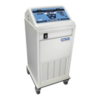
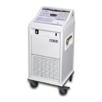
Figure 4-1 Micro-Temp
®
LT System – Maintenance Checklist