FIELD REPAIR/SERVICE MICRO-TEMP
®
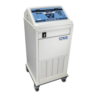
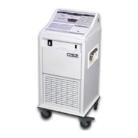
LT, Model 749
OPERATION AND TECHNICAL MANUAL
Page 48 of 75
G. Disconnect white and black pump lead wires.
H. Unscrew all four 8-32” Phillips head pump mounting screws from base.
I. Remove pump (with brackets and connecting hose between pump and reservoir still
attached) from enclosure.
J. Remove connecting hose from pump and set aside for later use.
K. Remove brackets from pump by unscrewing 8-32” nylon lock nut on stud of each
bracket.
L. Install brackets onto new pump, aligning the edges of the brackets with the edges of
the pump mount and tightening both brackets with a nylon lock nut.
M. Slide the connecting hose back onto the inlet of the pump. Be sure hose clamps are
loosely on connecting hose.
N. Insert pump into rear enclosure, making sure connecting hose properly aligns with
pump and reservoir.
O. Replace the four 8-32” Phillips head screws to the base.
P. Tighten both hose clamps on the connecting hose between the reservoir outlet and
the pump inlet.
Q. Reattach elbow to outlet of pump and replace wire tie.
R. Reconnect black and white pump lead wires to appropriate board wires.
S. Check that all cables are still attached to control board before closing unit.
T. Reconnect front and rear enclosure as described in Section (5-2.2).
U. Refill the reservoir as described in Section (4-2.2).