Chapter 3 - Drive System: Drive Shafts and Differentials
118
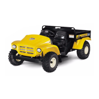
4b. The right side case half can also be
removed with the cartridge in-place.
See Figure 3.79.
• Press the shift fork in as the case halves are
separated.
• When the bearing race is clear of the bearing
cone, push the right case half in the direction of
the shift fork to disengage the fork from the dif-
ferential lock collar.
5. With the right half of the housing removed, the
differential assembly can be lifted out of the
housing. See Figure 3.80.
5a. The differential components and ring gear
are held together by one set of 3/8”-24 gr.
8 screws. With the screws removed, the
ring gear comes-off and the differential
can be separated. See Figure 3.81.
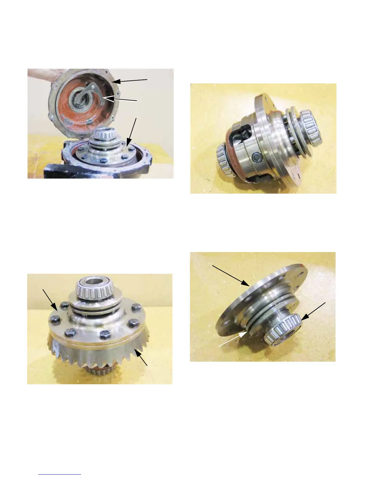
5b. If the carrier bearing is to be replaced, it
can be removed using a bearing puller.
The differential lock collar will slide-off
with the bearing removed.
See Figure 3.82.
5c. Four pins on the differential lock collar
engage four holes in the 16-tooth differen-
tial miter gear.
Figure 3.79
Right-side case
Differential
lock fork
Differential
assembly
Figure 3.80
Differential
assembly
Ring gear
Figure 3.81
ready to separate
less ring gear:
Differential housing,
Figure 3.82
Differential side plate
Differential
lock collar
Carrier
bearing
 Loading...