Chapter 2- Drive System: CVT and Transfer Case
42
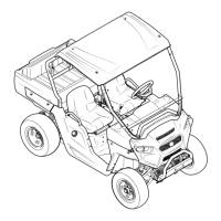
8a. Lift the input shaft assembly straight out of
the case. See Figure 2.92.
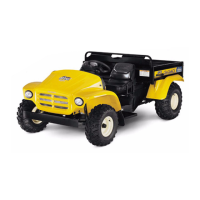
8b. The input shaft assembly consists of:
See Figure 2.93.
• A .060” (1.52mm) flat washer rides between the
low-gear pinion and the bearing that supports
the input shaft in the left case half.
• A 15-tooth low-gear pinion is positioned on the
first set of splines within the left case half.
• A 2-3/16” (55cm) spacer is placed between the
low gear pinion and the high-gear pinion.
• A 22-tooth high-gear pinion rides next to the
reverse pinion that is machined into the shaft.
9. Middle shaft and output shaft:
NOTE: The middle shaft gears all have features
that dictate their orientation during assembly.
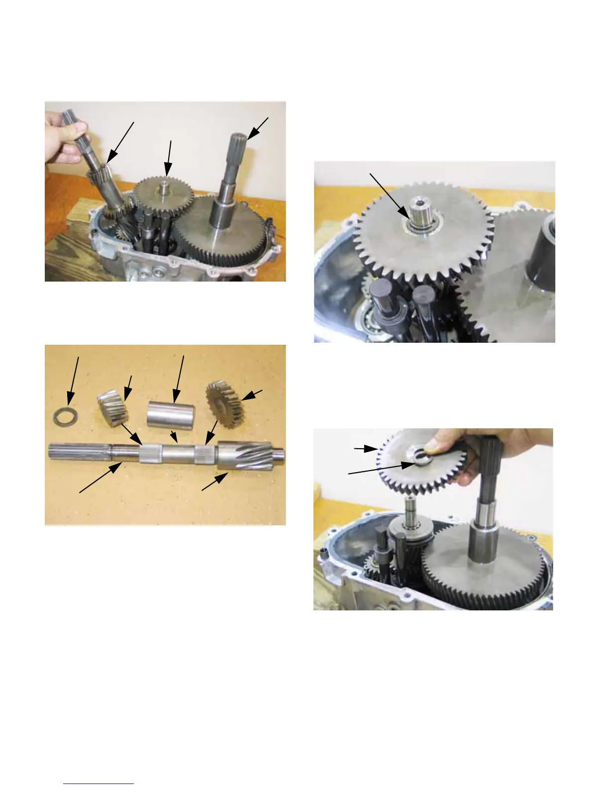
9a. Remove and discard the square-section
hog-ring from the end of the middle shaft.
See Figure 2.94.
9b. Lift the 40-tooth low gear off of the middle
shaft, along with the heavy washer that
separates it from the hog ring.
See Figure 2.95.
NOTE: It may take some wiggling, tugging, and
turning to loosen the gear, but it will come off.
Figure 2.92
Input shaft assembly
Middle shaft
Output shaft
Figure 2.93
.060” shim washer 2-3/16” Spacer tube
15-tooth low pinion 22-tooth forward
(high) pinion
Reverse pinion
Input shaft
Figure 2.94
Square-section hog ring
Figure 2.95
40-tooth
low gear
washer
 Loading...