HYDRO. DRIVE AND BRAKE SYSTEM
39
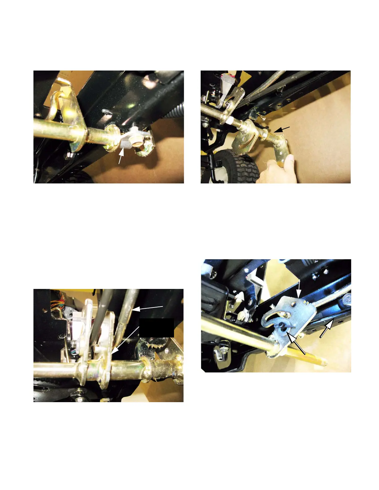
8. Loosen the bolt that holds the left pedal shaft
support strap using a 1/2” wrench.
See Figure 5.26.
9. Remove the bolt that holds the right pedal shaft
support strap using a 1/2” wrench.
NOTE: This will allow the pedal shaft assembly
to hang-down slightly on the right side of the
tractor.
10. Disconnect the drive control rod from the drive
pedal latch plate. See Figure 5.27.
• Remove and discard the cotter pin.
• Unhook the drive control rod.
Figure 5.26
Left pedal shaft support strap
Figure 5.27
Drive control
rod
Drive pedal
latch plate
11. Allow the drive pedal shaft to rotate down, then
pull it off of the pedal shaft assembly.
See Figure 5.28.
12. Disconnect the brake rod from the clutch/brake
latch plate. See Figure 5.29.
• Remove the cotter pin and flat washer to discon-
nect the brake rod. Discard the cotter pin.
• Unhook the brake rod from the clutch/brake latch
plate.
Figure 5.28
Drive control
pedal shaft
Figure 5.29
Brake rod
Flat washer
Clutch/brake
latch plate
 Loading...