CVT Drive and brake system
61
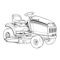
2. Visually inspect the linkage to confirm that it
functions properly. See Figure 6.9.
• Beneath the floor panel, on the right side of the
tractor there are two semi-circular latch plates.
• The outer latch plate rotates with the drive con-
trol pedals. The inner latch plate rotates with the
clutch/brake pedal.
2a. With the clutch/brake pedal fully released:
• The travel limit pin should be resting against the
front of the curved slot. See Figure 6.9.
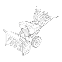
• The rod that connects the clutch/brake latch
plate to the heavy brake actuator spring should
be just slack. See Figure 6.10.
Figure 6.9
Travel limit pin
Clutch/brake latch plate:
fully released position
Figure 6.10
Brake spring
Brake rod
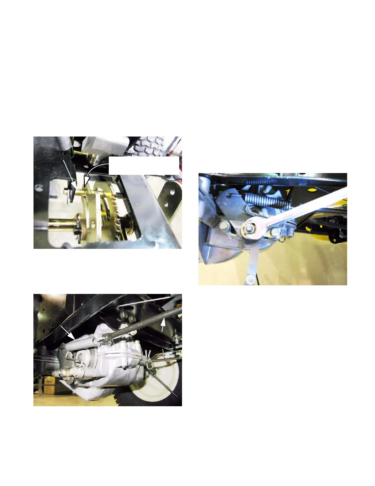
2b. Check the gap between the brake rotor
and the brake pads.
• There is a fixed pad in the transaxle housing.
• There is a moving pad in the brake caliper.
• Wiggle the brake rotor slightly, and attempt to
insert a .010” (.38mm) feeler gauge between the
rotor and either pad.
2c. Adjust the gap, if necessary, so that the
feeler gauge slips between the pad and the
rotor with light pressure. See Figure 6.11.
• Turn the nut to adjust the gap. The gap should
be in the range of .010”-.015” (.25mm-.38mm)
• Apply and release the brake pedal, then re-
check the gap.
2d. If the brake seems to be sticking, or the
rotor is discolored from dragging, remove
the brake yoke for repair or replacement.
2e. Set the brake. The front drive belt should
be slack.
2f. Re-test the operation of the brakes before
returning the tractor to service.
Figure 6.11
 Loading...