User Manual Control Units
www.cuesystem.com
Page 12 of 44
3.4.4. CUEwire Installation
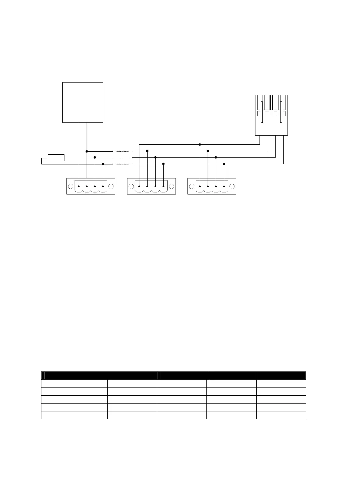
On the picture you can see a typical connection of CUEwire.
B-
A+
GND
+ 24 VDC
4-pin4-pin4-pin
Control Panel 1Control Panel 2Control Panel n
External power
supply
+ 24 VDC
GND
Assistant or Assistant-S
CUEwire (OUT RS-485)
120 ohm
4-pin
1 432
The cable consists of 4 wires. The first pair serves as a signal line. The second pair of wires serves for
power distribution. The signal conductors can have minimal 0,25 mm
2
, capacity maximal 100 pF/m.
The power distribution cable design depends on number of control panels to be connected and on the
required length of the cable. The maximum voltage loss on the whole power distribution conductors
should not exceed 4 V on the ground wire and 4 V on the +24 V wire.
To supply power distribution line the output OUT of the Assistant can be used. In this case the whole
consumption should not exceed 2 A (fuse in the Assistant and Assistant-S for power output marked
OUT is 2 A). In case of using more than 2 touchCUE units or for longer distances it is necessary to
use external power supply +24 V for remote panels (see example of the Panel n in the picture above).
Approximate consumption of control panels is
touchCUE ............................................1.0 A
keyboardCUE ......................................0.3 A
keyboardCUE-S...................................0.1 A
For the power consumption you can calculate 1 touchCUE = 3 keyboardCUE = 10 keyboardCUE-S.
Table of maximum cable lengths
Number of touchCUE Cable 1 mm
2
Cable 2 mm
2
Cable 3 mm
2
Cable 4 mm
2
1 200 m 400 m 600 m 800 m
2 100 m 200 m 300 m 400 m
3 60 m 130 m 200 m 260 m
4 50 m 100 m 150 m 200 m
5 40 m 80 m 120 m 160 m