User Manual Control Units
www.cuesystem.com
Page 6 of 44
3.2. Connectors
The following tables describe all ports comprehensively.
3.2.1. Assistant
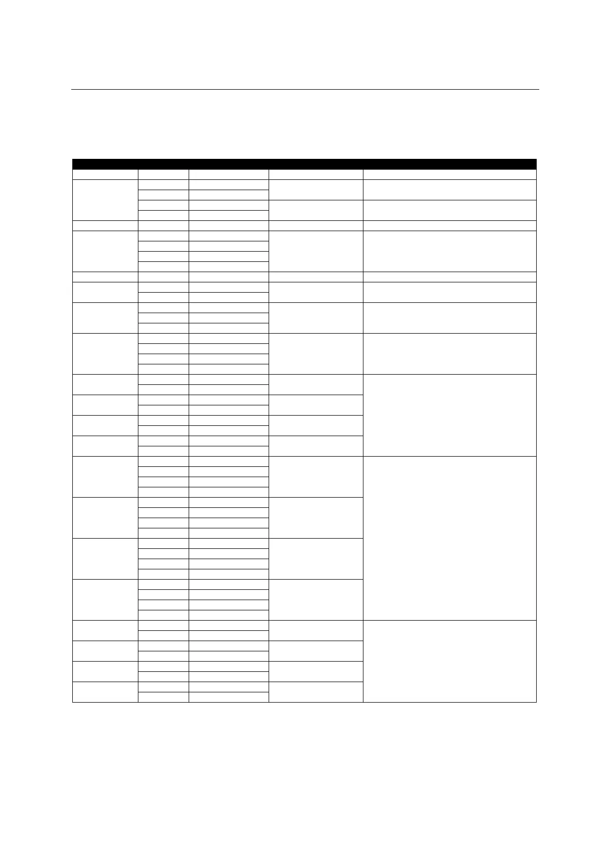
Label Pin nr. Meanin
Descri
tion Note
E 1a Earth
round
Protective
round
2a +24 V
3a Ground
Power output Power output with separate fuse
Ground = si
nal
round
4a In
ut/out
ut A+
CUEwire
(OUT RS-485)
5a In
ut/out
ut B-
RS-485 RS-485 bus connection
G 6a Ground
7a Out
ut
8a Ground
9a In
ut A+
CONSOLE
10a In
ut B-
Console (RS-232/422)
E 1b Earth
round
Protective
round
2b +24 V PWR
IN
3b Ground
Power input
4b Ground
5b In
ut
data
IR-REC
6b IR +12 V
IR input Input for
irCUE Receiver and old keyboardCUE models
7b S 9 out
8b S 9
round
9b S 9 in
ut A+
S9 / CUEring
10b S 9 in
ut B-
Serial I/O 9 Serial channel reserved for CUEring
11a IR 1 live IR 1
12a IR 1
round
Infrared output 1
13a IR 2 live IR 2
14a IR 2
round
Infrared output 2
11b IR 3 live IR 3
12b IR 3
round
Infrared output 3
13b IR 4 live IR 4
14b IR 4
round
Infrared output 4
General IR outputs
IR 1 is dedicated for keyboardCUE model ’97
15a Out
ut
16a Ground
17a In A+
S 5
18a In B-
Serial I/O 5
19a Out
ut
20a Ground
21a In A+
S 6
22a In B-
Serial I/O 6
15b Out
ut
16b Ground
17b In A+
S 7
18b In B-
Serial I/O 7
19b Out
ut
20b Ground
21b In A+
S 8
22b In B-
Serial I/O 8
Serial channels
23a A 1 live A 1
24a A 1
round
Analog output 1
25a A 2 live A 2
26a A 2
round
Analog output 2
23b A 3 live A 3
24b A 3
round
Analog output 3
25b A 4 live A 4
26b A 4
round
Analog output 4
Analog outputs 0 - 10 V