Chapter 2: Pre-Installation Planning
• If the bedrock is more than 3 meters (10 feet) below ground level, drive the grounding rod vertically
3 meters (10 feet) into the ground.
• If the bedrock is more than 1.2 meters (47 inches) below ground level, drive the rod into the ground
to bedrock level and bury the remainder horizontally at least 0.6 meters (2 feet) below ground level.
• If the bedrock is less than 1.2 meters (47 inches) deep, bury the rod horizontally at least 0.6 meters
(2 feet) below ground level.
NOTE: Refer to your local regulations and practices if an adequate grounding installation isn’t possible.
Rod Specifications for Grounding
The rod specifications are guidelines only. Refer to your national and local regulations for compliance
criteria.
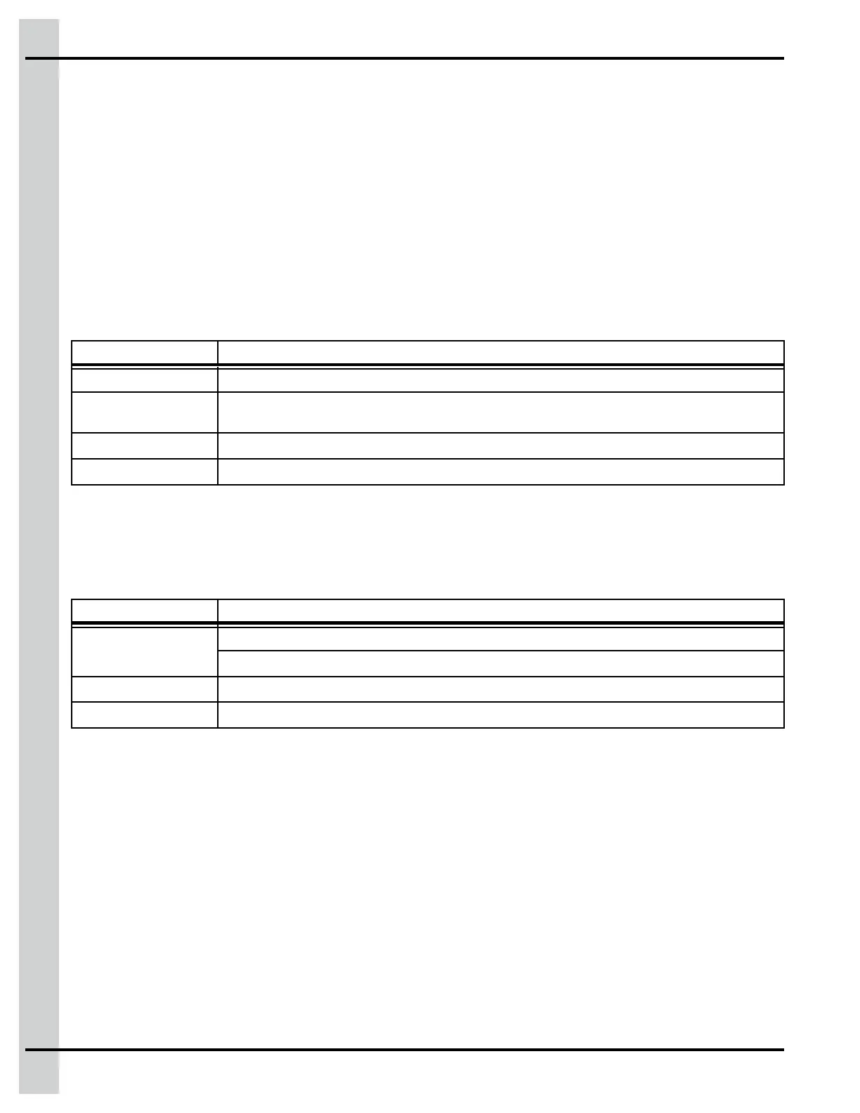
Table 2-1 Grounding rod specifications
Item Description
Material Metallic, normally steel core.
Rod surface The surface must be clean. It cannot be coated with paint, varnish or any non-conducting
substance.
Minimum diameter
16 mm (5/8 inches)
Minimum length
2440 mm (8 feet)
Cable Specifications for Grounding
The cable specifications are guidelines only. Refer to your national and local regulations for compliance
criteria.
Table 2-2 Grounding Cable Specifications
Item Description
Certification and
type
CSA, TEW type.
UL, 1015 type, 12 AWG, 600 V, 105 °C (221 °F), green/yellow insulated wire.
Maximum length
15 meters (50 feet)
Suggested cable Belden # 9912, color code 189, or equivalent
Installation Guidelines
Electrical Noise
• Install the controllers as far as possible from high voltage sources. It must be installed at least 24
inches (600mm) away from a Variable Frequency Drive (VFD).
• Never mount a power supply or transformer near the controllers. Allow at least 12 inches (300mm)
between them.
Cable Installation
• Ensure all cable entries are made through the bottom of the enclosures. Do not make holes through
the top or side panels of enclosure and be careful not to damage the electronic cards located inside
the enclosure when drilling.
• All incoming cables must connect directly to the terminals. No cabling should touch the side panels
or the top circuit board. Do not use the controller as a junction box.
34
890–00687 EDGE 2