Chapter 4: EDGE 2 Controller Installation
3. Using a level, make sure the enclosure is straight, and then screw in the second screw at the lower
right hand corner.
4. Screw in the last two screws.
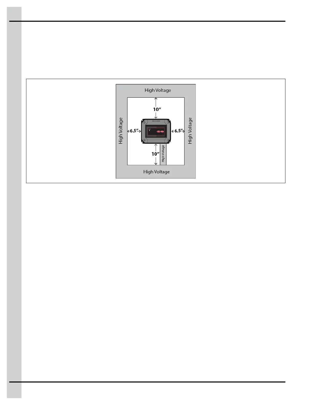
IMPORTANT: Leave minimum clearance of 22” W x 27” H to allow for proper circulation, cover
removal, and protection against electrically conducted noise.
Figure 4-2 Minimum clearance
Connecting a Module to the Communication Network
The communication bus enables communication between the EDGE 2 Controllers and the EDGE mod-
ules (terminal A and terminal B on the Automation network or the Safety network). There are two commu-
nication networks available. One of them serves as a backup network.
1. Locate the terminals Automation or Safety on the module you want to connect to the EDGE 3-Slot
or 6-Slot Expansion Box or EDGE 4IN-2V-8DO.
NOTE: You should always use the Automation network, unless you have redundant main controls.
2. Connect the wires from the module to the EDGE 3-Slot or 6-Slot Expansion Boxes or EDGE 4IN-2V-
8DO.
IMPORTANT: Make sure to connect same identifications together and use the same network from
one side to the other.
IMPORTANT: The communication network must be installed in a daisy chain topology. Consult the
wiring diagrams to see the maximum cable distance according to the wire gauge.
50
890–00687 EDGE 2