Part No. 4801-5338 Rev 2-2015 Evolution 4000 17 of 86
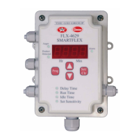
NOTE: Run Time in seconds
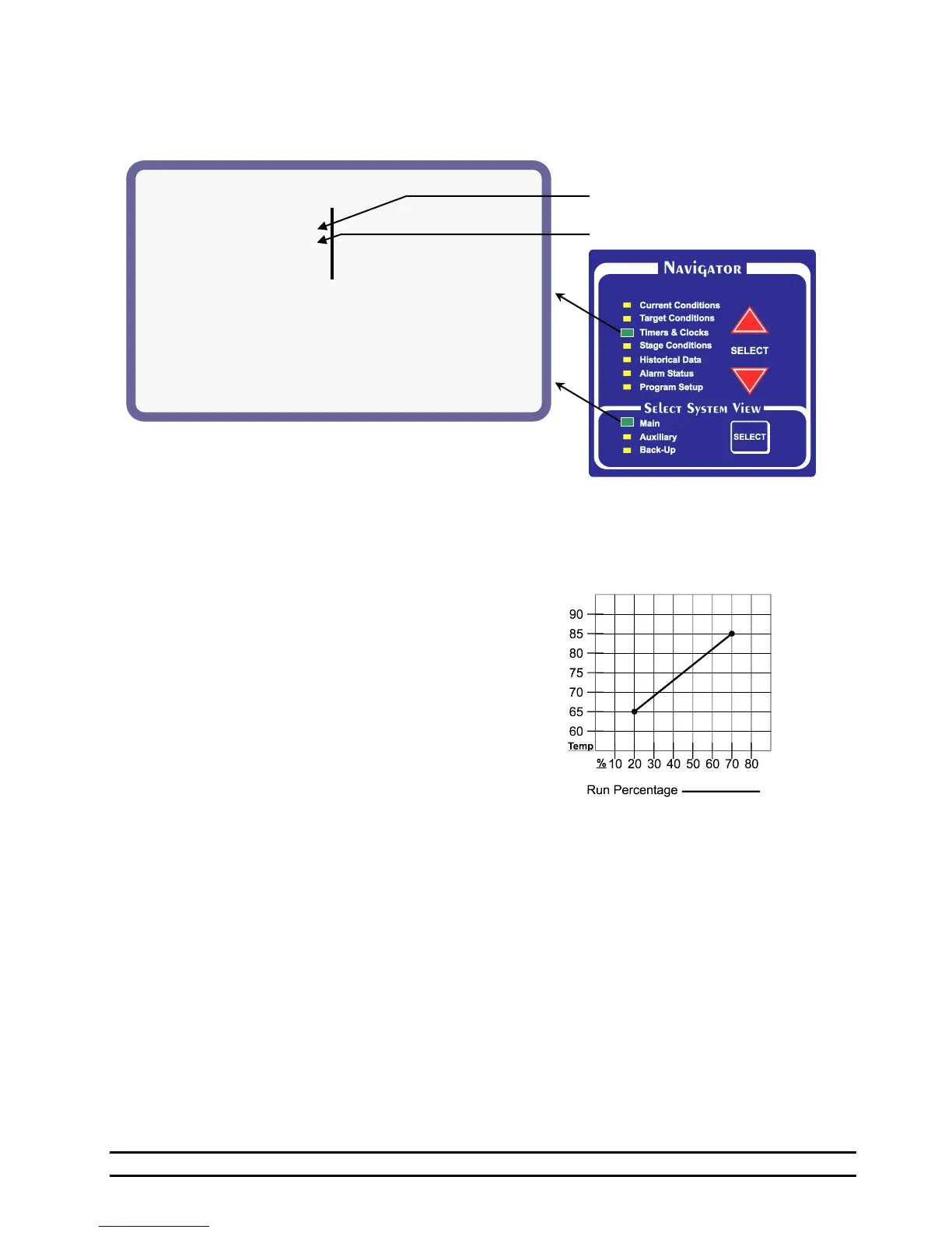
6.3 Timers & Clocks – MAIN SYSTEM
The Minimum Vent status screen display:
(1) Light Schedule – Displays the current Light Clock
Schedule. See Section 7.13.
(2) Feed Schedule – Displays the current Feed Clock
Schedule. See Section 7.12.
(3) Minimum Timer 1 - The Minimum timer one and
two both share the same cycle time. Different timer
percentages may be set for minimum 1 vs. minimum
2. If the vent anticipation is being used, the vents
will start opening before a negative ventilation stage
turns on and will adjust until the vent opening
necessary for the desired target pressure is achieved.
(4) Cycle - The length of Timer 1 cycle. Cycle = 1 to
20 minutes.
(5) Min1 % - The percentage of the Timer 1 cycle that
the stage will run.
(6) Min2 % - The percentage of the Timer 2 cycle that
the stage will run.
(7) Var % - The percentage of time a stage is currently
running using the variable timer based off the
temperature.
NOTE: The Minimum timer one and two both share
the same cycle time. Different timer percentages
may be set for Minimum 1 and Minimum 2. If the
vent anticipation is being used, both Minimum 1 and
Variable will start the vents open before a stage
comes on.
(8) Variable Speed: These settings are used to set up
variable speed fan operation.
(9) V1 Minimum - The minimum speed or minimum
percentage of light intensity for V1; The value
inside the parenthesis shows the current percentage.
(10) V2 Minimum -The minimum speed or minimum
percentage of light intensity for V2; The value
inside the parenthesis shows the current percentage.
(11) Variable Timer - The variable timer will vary the
timer based on temperature. See chart shown
below.
(12) Sensors - The sensors used to determine the run
time. Active sensors will be indicated by a number
starting with #1 from right to left. Inactive sensors
will be indicated by a - or hyphen. When "outside-"
is displayed, outside sensor is active. For example, If
sensors 1, 2 and 3 are being used, "-----321" will be
displayed. When “outside” is displayed, the outside
sensor is active.
(13) Max Run % - The maximum Run Time
percentage.
(14) Max Temp - The temperature at which the timer
will run Maximum Run time % percentage.
(15) Min Run % - The minimum Run Time
percentage.
(16) Min Temp - The minimum temperature. The
timer will be at minimum Run %.