Part No. 4801-5338 Rev 2-2015 Evolution 4000 48 of 86
A/D Readings:
These values will be used to troubleshoot your controller by a qualified service technician in the event that a problem
occurs with your PCB194 I/O board or connected analog and digital input devices.
The display view shown below is the bottom portion of the Program Setup > Diagnostics screen. These values
represent the information being received from various I/O connections.
Temp 1 through Temp 8 and the Outside Temp will display Analog-to-Digital values which represent the
temperature for the specific temperature sensor. The value may be from 0-256. Refer to the A-to-D / Temperature
chart provided in Section 10.
Humidity 1 and Humidity 2 will display Analog-to-Digital values which represent the humidity for the specific
Humidity Sensor. The value may be from 0 to 256 (0-100% Relative Humidity).
Feed 1 and Feed 2 will display Analog-to-Digital values which represent the current feed level for the specific
feed bin. The value may be from 0-256. Refer to the Feed Level Sensor Inputs chart below.
The GP 1 analog input is a spare input which can be used for alternate analog devices. The value may be from 0-
256.
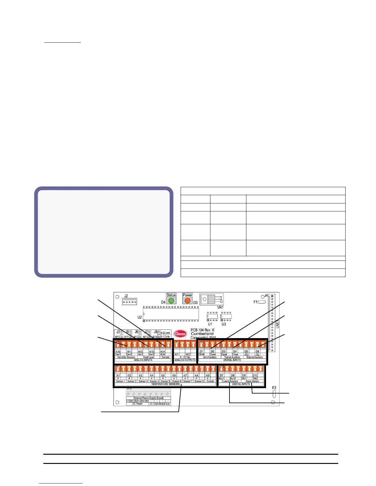
The Vent Opened, Tunnel Closed, Curt 1/2/3/4 Closed, Water 1&2, Run 1&2 are all digital inputs which are
toggled from either No to Yes or from Off to On by an open circuit or closed circuit (shorted condition to ground).
The conditions shown in the sample display window below are with open circuits or otherwise unconnected
terminal blocks. The terminal block Natural Auxiliary U1 Close (Curt 1) & U2 Close (Curt 2) are quickly
identified although Curt 3 and 4 connections are located at Vent Auxiliary Close (Curt 3) and Tunnel Auxiliary
Open (Curt 4).
Feed 1 & Feed 2 - Feed Level Sensor Inputs
Feed is on or above proximity rod.
Bin may be empty or a sensor error
Value should be based on level of
feed with 58 being approximately full.
Could represent empty but probably
a defective sensor.
Temp 1 – Temp 8 &
Outside Temperature
Sensor Inputs
Run 1 & Run 2
Current Sensor Inputs
Water 1 & Water 2
Meter Inputs
Humidity 1 &
Humidity 2
Inputs