Do you have a question about the Current Tools Omni 747 and is the answer not in the manual?
Explains the purpose and meaning of the safety alert symbol used in the manual.
Defines the terms DANGER, WARNING, and CAUTION used for safety warnings.
Covers safe use of power sources, cords, and grounding for the bender.
Details safe handling, positioning, and personal protective equipment recommendations.
Details physical attributes, power needs, and bending capabilities of the 747 Omni Bender.
Lists the primary features and advantages of the bender design and functionality.
Provides data on bend radii for various conduit types and sizes.
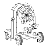
Illustrates and labels the main components visible from the front of the bender.
Illustrates and labels the main components visible from the rear of the bender.
Explains the critical need for proper grounding and GFCI protection for safe operation.
Step-by-step guide to rotate the bender power unit into a horizontal position.
Instructions on how to roll or lift the bender for transportation.
Steps to secure the bender using leveling screws and locking casters.
Instructions for rotating the bender power unit to the vertical operating position.
Details connecting the power cord and turning on the circuit breaker.
Guide to choosing, removing, and attaching the correct bending shoe for conduit.
Instructions for setting the bend degree pointer to the initial -10° position.
How to align drive studs with the bender's mounting holes for secure attachment.
How to adjust the limit switch for accurate and repeatable bend angles.
Explains the internal stop switch that prevents damage to shoe/roller assembly.
Basic troubleshooting for issues with the bend angle limit switch operation.
Explains how the return spring positions the support rollers after bending.
Steps for attaching the pin-on roller support for 1/2" to 1-1/4" conduit.
How to mark conduit and correctly position it within the bender.
Procedures for executing a bend and safely releasing the conduit.
How to install the pin-on roller support for 1-1/2" and 2" conduit.
Marking conduit and setting the bend angle limit for larger sizes.
Steps for engaging rollers and adjusting the squeeze feature.
Finalizing the bend, releasing conduit, and checking for marks or wrinkles.
Guide for using the specific shoe and roller support for PVC coated rigid conduit.
Detailed steps for bending PVC coated rigid conduit accurately.
Instructions for physically moving and securing the bend degree pointer.
Explains the necessary gap between pointer and limit switch.
Guide to calculating and marking conduit for stub-up bends using springback charts.
Table showing springback values for Rigid Conduit/Schedule 40 Pipe.
Table showing springback values for EMT Conduit.
Table showing springback values for IMC Conduit.
Table showing springback values for PVC Coated Rigid Conduit.
Guide to marking conduit for offset bends using charts and springback data.
Provides charts (D and E) for calculating offset dimensions and multipliers.
Details oil type, quantity, and flushing for the gear box.
Procedures for checking and adjusting front and rear chain tension.
How to adjust the spring tension for the bend angle limit switch.
Recommends lubrication schedule and method for roller supports.
Diagnoses problems related to no power, motor function, and one-direction operation.
Addresses issues with the bend angle limit switch and contactor chatter.
Diagrams showing numbered parts for the front and rear assemblies of the bender.
Identifies parts for the chassis, wheels, casters, and leveling screws.
Details parts for the roller support arm, plates, and various rollers.
Lists components related to the cam shaft, lever, fittings, and springs.
Identifies parts for the electrical plate, switches, and remote pendant.
Details parts for urethane and 4-roller support assemblies.
Lists components for the 1/2" to 1-1/4" bending shoe assembly.
Lists components for the 1-1/2" to 2" bending shoe assembly.
Lists parts for the PVC coated bending shoe assembly.
Lists components for the PVC coated roller support assembly.
Lists parts for frame, chain, sprockets, controls, guards, and motor/gearbox.
Comprehensive list of electrical components including transformers, relays, switches, and connectors.
Illustrates the electrical connections and component layout for the bender.
| Brand | Current Tools |
|---|---|
| Model | Omni 747 |
| Category | Cutter |
| Language | English |