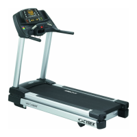
Cybex 425T Treadmill Service Manual
4. Connect the cables to the lower control board.
A. Connect the cables from the lower control board. This includes: the elevation motor
cables (COM, UP, DOWN and GND); Ground cable; elevation switch (P1); display
cable (P3); speed sensor (P2); display cable (P4); AC line hot, black (AC1); AC line
neutral, white (AC2); drive motor cable red (A1) and drive motor cable black (A2). See
Figure 17.
5. Secure the wires.
A. Check to see that all of the cables are connected firmly in their proper place.
NOTE: The calibration procedure will need to be completed after replacing the lower control
board. Follow the Speed Calibration procedure located in this chapter.
Power Cord
Tools Required
• 3/8” Nutdriver or socket wrench
• ESD (Electro Static Discharge) grounding strap
! WARNING: Disconnect the power cord before beginning this procedure. Keep wet
items away from inside parts of the treadmill. Electrical shock could occur
even if the treadmill is unplugged. Do not touch components on the lower
board. A charge can remain after unplugging the power cord.
6. Disconnect the external power source.
A. Unplug the treadmill from the power outlet.
7. Remove power cord.
A. Using a 3/8” nutdriver or socket wrench remove the nut securing the ground wire to
the motor base plate. See Figure 18.
B. Unplug the black and white fast-on connectors from the circuit breakers. See
Figure 18.
C. Remove the old power cord and discard.
8. Install the power cord.
A. Insert the new power cord throught the strain relief in the motor base plate.
B. Using a 3/8” nutdriver or socket wrench secure the ground wire to the motor base
plate.
NOTE: Each circuit breaker must have the same color cable connected to it. DO NOT mix the
black and white wires.
C. Connect the black fast-on connectors from the power cord to the circuit breaker with
the black wire. See Figure 18.
Service
Page 4-22

 Loading...