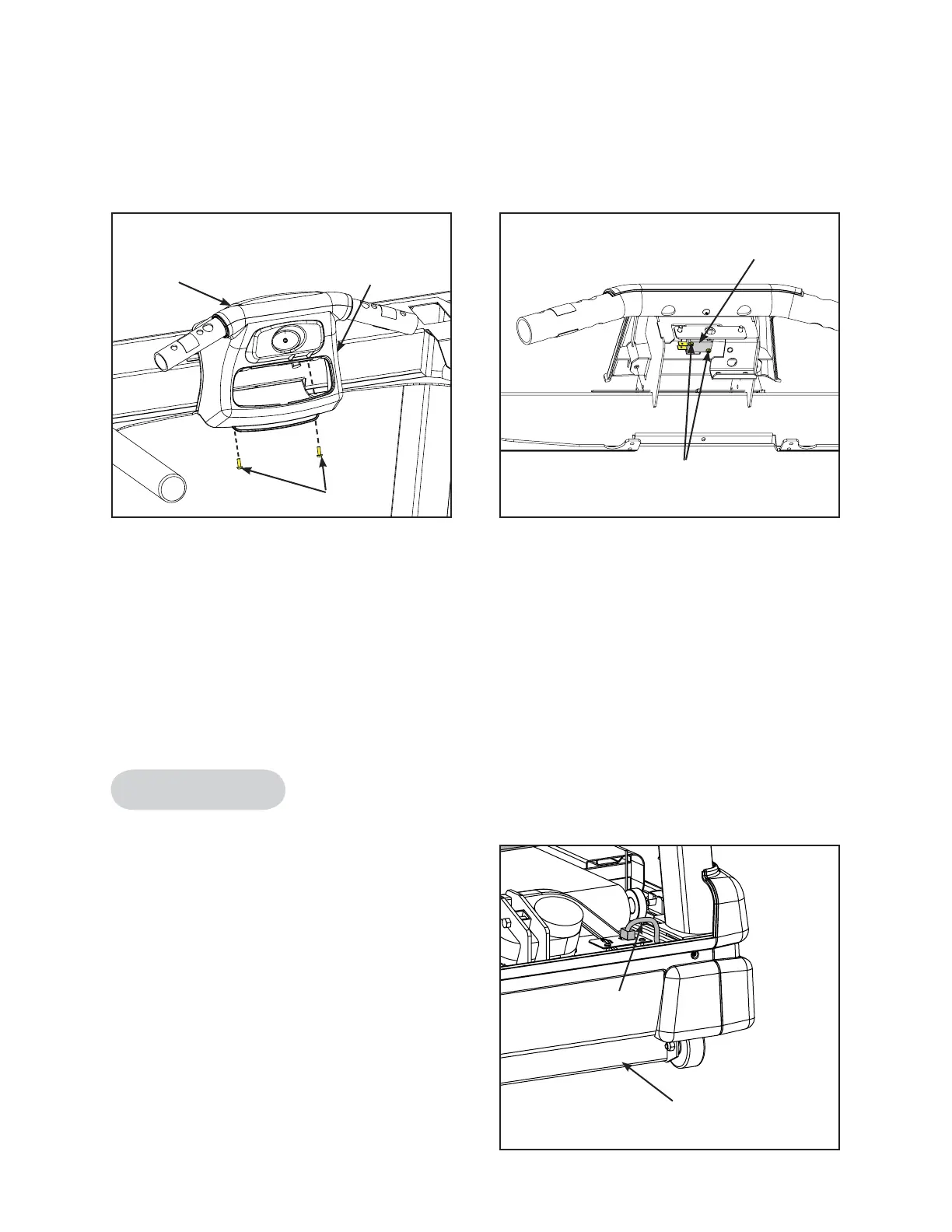
10. Remove the lower handle cover.
A. Using a Philips head screwdriver remove the two screws securing the lower handle
cover to the upper handle cover. See Figure 27.
11. Remove the e-stop switch.
A. Using a Philips head screwdriver remove the two screws securing the e-stop switch.
See Figure 28.
12. Install the e-stop switch.
A. Using a Philips head screwdriver install the two screws securing the e-stop switch.
See Figure 28.
Display Cable
Tools Required
• Wire cutters
13. Remove the display cable.
A. Disconnect the display cable from the
connector plate in the base. See Figure
29.
B. Using wire cutters, cut the wire ties on
top of the handrail and the contact heart
rate cable.
C. Pull the display cable out of the handrail.
Cybex 425T Treadmill Service Manual
Service
Page 4-32
Figure 27
Screws
Upper
Handle
Cover
Lower
Handle
Cover
Figure 28
Screws
E-Stop
Switch
Figure 29
Display
Cable
Base
 Loading...