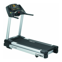
Cybex 425T Treadmill Service Manual
Service
Page 4-20
7. Install Drive motor.
! WARNING: Drive Motor is heavy, use care when lifting.
A. Lift the drive motor up and into the motor base plate.
B. Using a 1/2” socket with a 6” extension secure the drive motor to the motor base plate
using four mounting nuts.
8. Connect the motor cables.
A. Locate the red and black drive motor cables exiting the drive motor.
B. Connect the two motor cables from the lower board. ! WARNING: Avoid touching
lower board components such as resistors and capacitors.
C. Install the ferrite from the two motor cables.
D. Using wire ties secure the drive motor cables to the lower control board bracket.
NOTE: The calibration procedure will need to be completed after replacing the drive motor.
Follow the Speed Calibration procedure located in this chapter.
Lower Control Board
NOTE: This procedure will cover the lower control board, power cord, circuit breakers and
line filter. Follow this procedure from step 1 even though the heading for some of
these procedures will appear before the step where you remove that part.
Tools Required
• Phillips head screwdriver
• ESD (Electro Static Discharge) grounding strap
! WARNING: Disconnect the power cord before beginning this procedure. Keep wet
items away from inside parts of the treadmill. Electrical shock could occur
even if the treadmill is unplugged. Do not touch components on the lower
board. A charge can remain after unplugging the power cord.
1. Disconnect the cables from the lower control board.
A. Disconnect the cables from the lower control board. This includes: the elevation motor
cables (COM, UP, DOWN and GND); Ground cable; elevation switch (P1); display
cable (P3); speed sensor (P2); display cable (P4); AC line hot, black (AC1); AC line
neutral, white (AC2); drive motor cable red (A1) and drive motor cable black (A2). See
Figure 17.

 Loading...