Cybex 425T Treadmill Service Manual
Service
Page 4-28
Upper Display Board
NOTE: This procedure will cover the upper display board, display overlays, contact heart rate
grips, e-stop switch and display cable.
Tools Required
• Phillips head screwdriver
• ESD (Electro Static Discharge) grounding strap
1. Disconnect the external power source.
A. Unplug the treadmill from the power outlet.
NOTE: The display board is susceptible to damage from a discharge of static electricity.
While handling parts underneath
the console cover use an ESD
grounding strap. This eliminates
the potential voltage (static)
difference between you and the
equipment you are working on.
Wear an ESD strap for the rest of
this procedure.
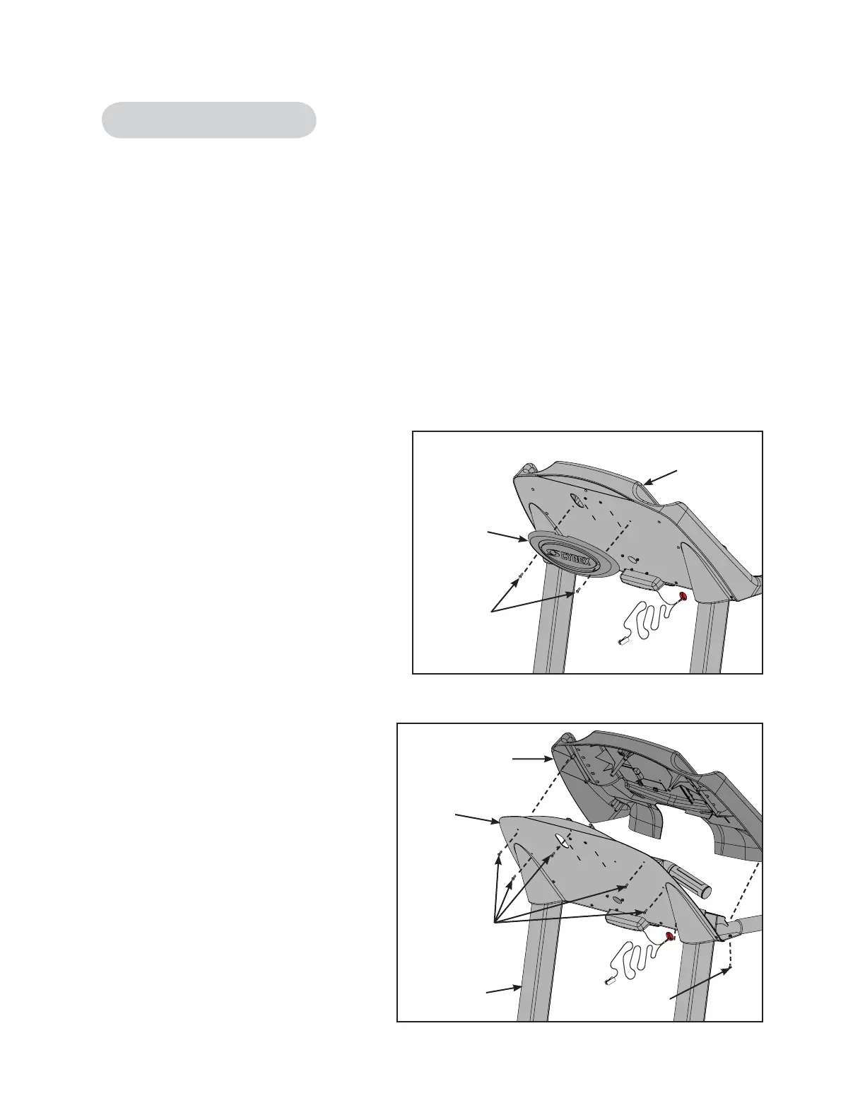
2. Remove the console assembly
from the handrail.
A. Using a Philips head screwdriver
remove the two screws securing
the back cover to the console
assembly. See Figure 20.
B. Using a Philips head
screwdriver remove the two
machine screws securing the
console assembly to the upright
assembly. See Figure 21.
C. Using a Philips head
screwdriver remove the seven
screws that hold the console
assembly to the console back.
See Figure 21.
D. Gently tilt the concole assembly
forward and disconnect these
cables from the display board:
the display cable (2 connectors),
the contact heart rate cable, the
Polar cable and the ground wire.
See Figure 22.
Figure 20
Console
Assembly
Back
Cover
Screws
Figure 21
Screws
Machine Screw
Console
Assembly
Upright
Assembly
Console
Back
 Loading...