2 Installation
2.1 Mounting Location
Choose the mounting locations carefully before you drill or cut. The unit should be mounted so that
the operator can easily use the controls and clearly see the screen. Be sure to leave a direct path for
all of the cables. The unit has a high-contrast screen, and is viewable in direct sunlight, but for best
results install the unit out of direct sunlight. The chosen location should have minimal glare from
windows or bright objects. Choose an area where the unit will not be subjected to excessive vibration,
or heat. Good ventilation is required.
Warning!: Inadequate ventilation may cause the unit to overheat. The unit is designed to
operate in temperatures from -15° C to +55° C (+5° F to +131° F).
2.2 Panel Mounting
The screws and gasket used for panel mounting are included in the box. For mounting instructions,
refer to the Panel mounting template.
2.3 Wiring
Warning!: Before starting the installation, be sure to turn electrical power off. If power is left on
or turned on during the installation, fire, electrical shock, or other serious injury may occur. Be
sure that the voltage of the power supply is compatible with the unit.
Warning!: The unit has a voltage rating of 12 V DC, it is not suited for use with 24 V DC
systems.
The unit is powered by 12 V DC. It is protected against reverse polarity, under voltage, and over
voltage (for a limited duration). The plug of the supplied power cable has two discrete cables exiting
from it. The thickest of the two cables provides the following:
Power into the system (Red and Black wires).
Controlling power state of the unit (Yellow wire)
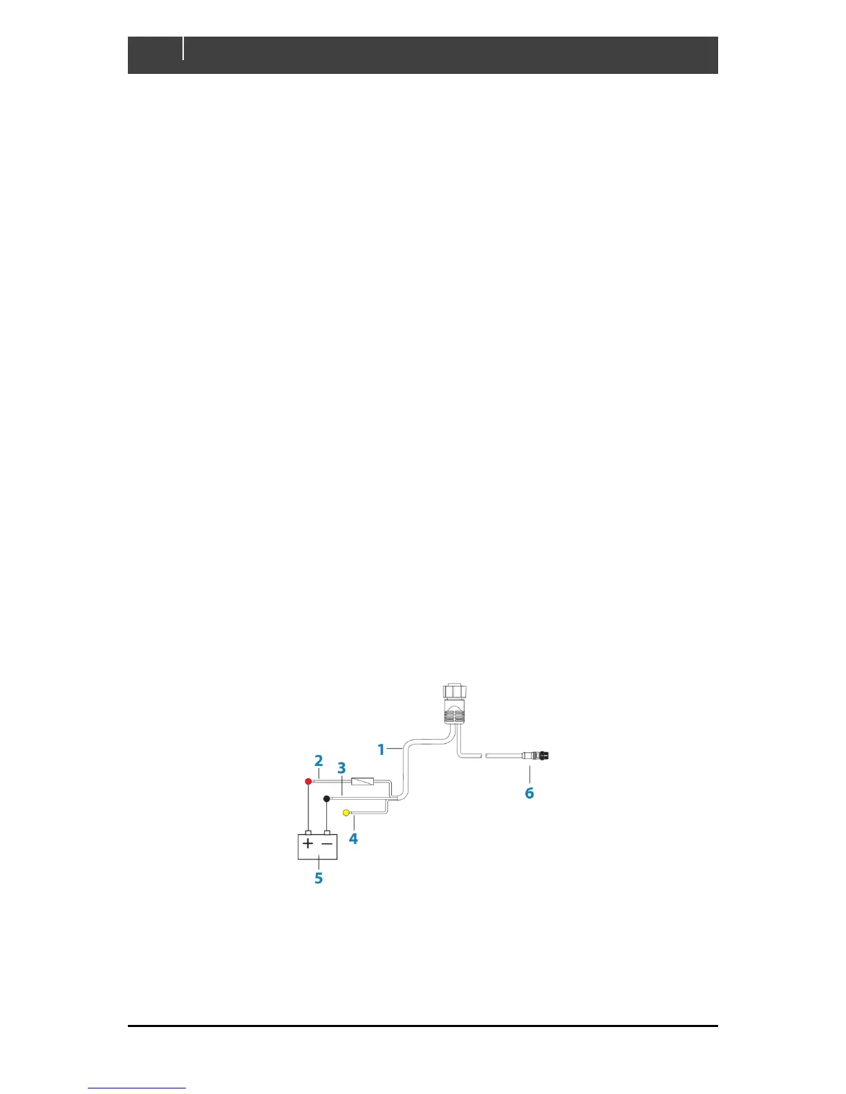
Figure 1. Battery & Power Connections
1. Power cable
2. 12 V DC positive wire (red) shown with fuse holder fitted
3. 12 V DC negative wire (black)
4. Power control wire (yellow)