Pilot's Operating Handbook
Section 7
Description
Edition 0 - March 05, 2019
Rev. 3
Page 7.8.1
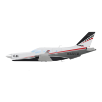
7.8 - Fuel system - see figures 7.8.1 and 7.8.1A
The fuel system comprises fuel tanks, fuel unit, selectors, manual and automatic,
electric and mechanical boost pumps, engine fuel system, gaging installation,
monitoring installation and drains.
Fuel tanks
Fuel tanks are formed by sealed casings in each wing. Each fuel tank comprises a
filling port located at the end of wing upper surface, two drain valves located at the
lower surface (one near main landing gear, at trailing edge side, the second one near
wing root side, at leading edge), a vent valve located on the lower surface, a suction
strainer and three level gages.
Fuel unit
The fuel unit combines shut-off valve, tank selector and filterfunctions. Itisconnected
to th
e manual selector through a mechanical control. The fuel filter is located in a bowl
at the lower part of the unit. It is fitted with a by-pass valve, a clogging indicator and a
drain valve.
>> With HomeSafe emergency function (Post-MOD70-0650-34A)
HomeSafe fuel shut-off valve
HomeSafe shuts down the engine after landing by closing a fuel shut-off valve in the
line between the right fuel tank and the fuel selector.
HS FUEL SHUTOFF is displayed in the CAS window if the shut-off valve is closed.
The HomeSafe fuel shut-off valve is prevented from closing when the AUX BP switch
isON.If HS FUEL SHUTOFF is ON when the AUXBP switch is ON, itmay indicate a
mechanical failure of the HomeSafe fuel shut-off valve.
>> All
Tank manual selector - see figure 7.8.2
The FUEL TANK SELECTOR is located on the pedestal rear face. It allows selecting
manually the tank (R or L) to be used and setting unit to OFF. To change from L
position to OFF position, turn the selector clockwise (L → R → OFF) ; change from R
position to OFF position requires a voluntary action from the pilot (pull and turn). The
pull and turn maneuver prevents involuntary operation. When the unit is set to OFF,
FUEL OFF remains visible.