User’s Manual
38
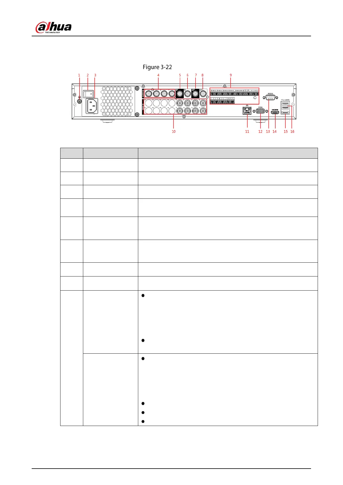
3.2.10 DH-XVR5408L-X
Rear panel
Table 3-19 Rear panel description
1 GND Ground.
2 Power button Turns on/off the Device.
3 Power input port Inputs power.
4 Audio input port
Receives the analog audio signal output from the devices such as
microphone.
5
Audio input port
(MIC IN)
Tow-way talk input port which receives
output from the devices such as microphone, pickup.
6
Audio output port
(MIC OUT)
Tow-way talk output port which outputs the analog audio signal to
the devices such as the sound box.
7
Audio output port
Outputs the analog audio signal to the devices such as the sound box.
8 Video output port
Connect to video output devices such as TV.
9
Alarm input port 1–
16
Four groups of alarm output ports (Group 1: port 1 to port 4;
Group 2: port 5 to port 8; Group 3: port 9 to port 12; Group 4:
port 13 to port 16). These ports receive the signal from the
external alarm source. There are two types; NO (Normally Open)
and NC (Normally Closed).
When your alarm input device is using external power, make sure
that the device and the NVR have the same ground.
1–5 (NO1–NO5;
C1–C5; NC5)
Five groups of alarm output ports. (Group 1: port NO1–C1,Group
2:port NO2–C2,Group 3:port NO3–C3, Group 4:port NO4–C4,
Group 5: port NO5, C5, NC5). These ports output alarm signal to
the alarm device. Make sure that power supply to the external
alarm device.
NO: Normally open alarm output port.
C: Alarm output public end.
NC: Normally closed alarm output port.
 Loading...