User’s Manual
60
Table 4-32 Relay activation parameter
Parameter Description
Anti-dither Enter anti-dither time. It ranges from 0s to 100s.
Sensor Type
Select relay-in type according to the connected alarm input device.
NO: Low level valid.
NC: High level valid.
Relay-out
Optocoupler output, select the check box to activate corresponding alarm
output device when alarm occurs.
Signal Duration The time that delays alarm when alarm occurs.
Step 5 Click Confirm.
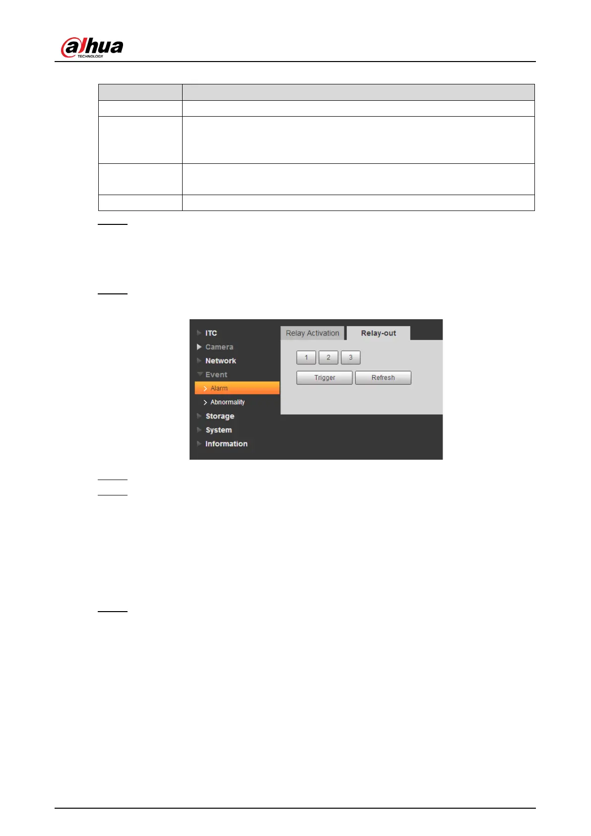
4.5.4.1.2 Relay-out
In this section, you can trigger one alarm output signal.
Step 1 Select Setup > Event > Alarm> Relay-out.
Figure 4-64 Relay-out
Step 2 Click 1, 2 or 3, and set 1 channel of alarm channel.
Step 3 Set alarm output.
Click Trigger to output relay-out signal.
Click Refresh to refresh alarm output status.
4.5.4.2 Abnormality
This section provides guidance on setting relay-out mode of different events.
Step 1 Select Setup > Event > Abnormality.
The Abnormality interface is displayed. See Figure 4-65, Figure 4-66, Figure 4-67,
Figure 4-68, Figure 4-69 and Figure 4-70.
 Loading...