Page.88.
short circuit, help engineer quickly find the cable’s problem location. It is more convenient and efficient
to repair the faulty cable.
Note: The TDR reflect signal could be affected by the cable quality/ cable’s not well
connected etc to cause the different TDR measurement, the TDR measurement is for reference
only.
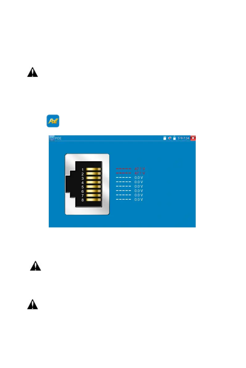
Click icon to enter PoE voltage measurement
Connect a network cable from a PoE switch to the tester’s PSE IN port. Connect an IP camera or other
PoE using node to the tester’s LAN port, the PoE voltage and the cable’s pin connection status show on
the screen.
Note: This test if for measuring the voltage being drawn by the PoE node and the tester
must be between the PoE switch and the PoE node for this test to work.
Note: The PoE switch must be connected to the PSE IN port. The powered device such as IP
camera or other PoE node must be connected to the LAN port.
Note: Do not connect PoE power supply equipment (such as a PoE switch) to the tester’s
UTP/SCAN port; otherwise it will damage the tester.
PSE transmission
 Loading...