6Installation
Installerreferenceguide
11
AZQS100~140B8V1B+AZQS100~140B7Y1B
Splitsystemairconditioners
4P3855291–2014.08
▪ Keepinginmindtheguidelinesfor:
▪ Pipebending
▪ Flaringpipeends
▪ Brazing
▪ Usingthestopvalves
6.4.2 Precautionswhenconnectingthe
refrigerantpiping
INFORMATION
Also read the precautions and requirements in the
followingchapters:
▪ Generalsafetyprecautions
▪ Preparation
DANGER:RISKOFBURNING
CAUTION
▪ DoNOTusemineraloilonflaredpart.
▪ NEVER install a drier to this R410A unit to guarantee
its lifetime. The drying material may dissolve and
damagethesystem.
NOTICE
Take the following precautions on refrigerant piping into
account:
▪ Avoid anything but the designated refrigerant to get
mixedintotherefrigerantcycle(e.g.air).
▪ OnlyuseR410Awhenaddingrefrigerant.
▪ Onlyuseinstallationtools(e.g.manifoldgaugeset)that
are exclusively used for R410A installations to
withstandthepressureandtopreventforeignmaterials
(e.g. mineral oils and moisture) from mixing into the
system.
▪ Installthepipingsothatthe flare is NOT subjected to
mechanicalstress
▪ Protectthepipingasdescribedinthefollowingtableto
preventdirt,liquidordustfromenteringthepiping.
▪ Usecaution whenpassingcopper tubesthroughwalls
(seefigurebelow).
Unit Installationperiod Protectionmethod
Outdoorunit >1month Pinchthepipe
<1month Pinchortapethepipe
Indoorunit Regardlessofthe
period
INFORMATION
Do NOT open the refrigerant stop valve before checking
therefrigerantpiping.Whenyouneedtochargeadditional
refrigerantitisrecommendedto open the refrigerant stop
valveaftercharging.
6.4.3 Guidelineswhenconnectingthe
refrigerantpiping
Takethefollowingguidelinesintoaccountwhenconnectingpipes:
▪ Coat the flare inner surface with ether oil or ester oil when
connecting a flare nut. Tighten 3 or 4 turns by hand, before
tighteningfirmly.
▪ Alwaysusetwowrenchestogetherwhenlooseningaflarenut.
▪ Alwaysuse a spannerandtorque wrenchtogetherto tightenthe
flarenutwhenconnectingthepiping.Thistopreventnutcracking
andleaks.
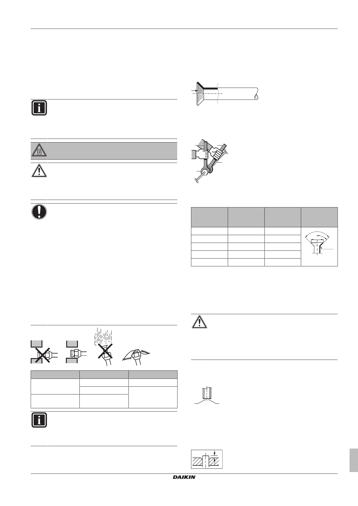
a Torquewrench
b Spanner
c Pipingunion
d Flarenut
Pipingsize
(mm)
Tightening
torque(N•m)
Flare
dimensions(A)
(mm)
Flareshape
(mm)
Ø6.4 15~17 8.7~9.1
Ø9.5 33~39 12.8~13.2
Ø12.7 50~60 16.2~16.6
Ø15.9 63~75 19.3~19.7
Ø19.1 90~110 23.6~24.0
6.4.4 Pipebendingguidelines
Usea pipebenderfor bending.All pipebendsshould beasgentle
aspossible(bendingradiusshouldbe30~40mmorlarger).
6.4.5 Toflarethepipeend
CAUTION
▪ Incompleteflaringmaycauserefrigerantgasleakage.
▪ Do NOT reuse flares. Use new flares to prevent
refrigerantgasleakage.
▪ Use flare nuts that are included with the unit. Using
differentflarenutsmaycauserefrigerantgasleakage.
1 Cutthepipeendwithapipecutter.
2 Removeburrswiththecutsurfacefacingdownwardsothatthe
chipsdonotenterthepipe.
a Cutexactlyatrightangles.
b Removeburrs.
3 Removethe flarenutfromthestopvalveandputtheflarenut
onthepipe.
4 Flare the pipe. Set exactly at the position as shown in the
followingillustration.