12Technicaldata
Installerreferenceguide
30
AZQS100~140B8V1B+AZQS100~140B7Y1B
Splitsystemairconditioners
4P3855291–2014.08
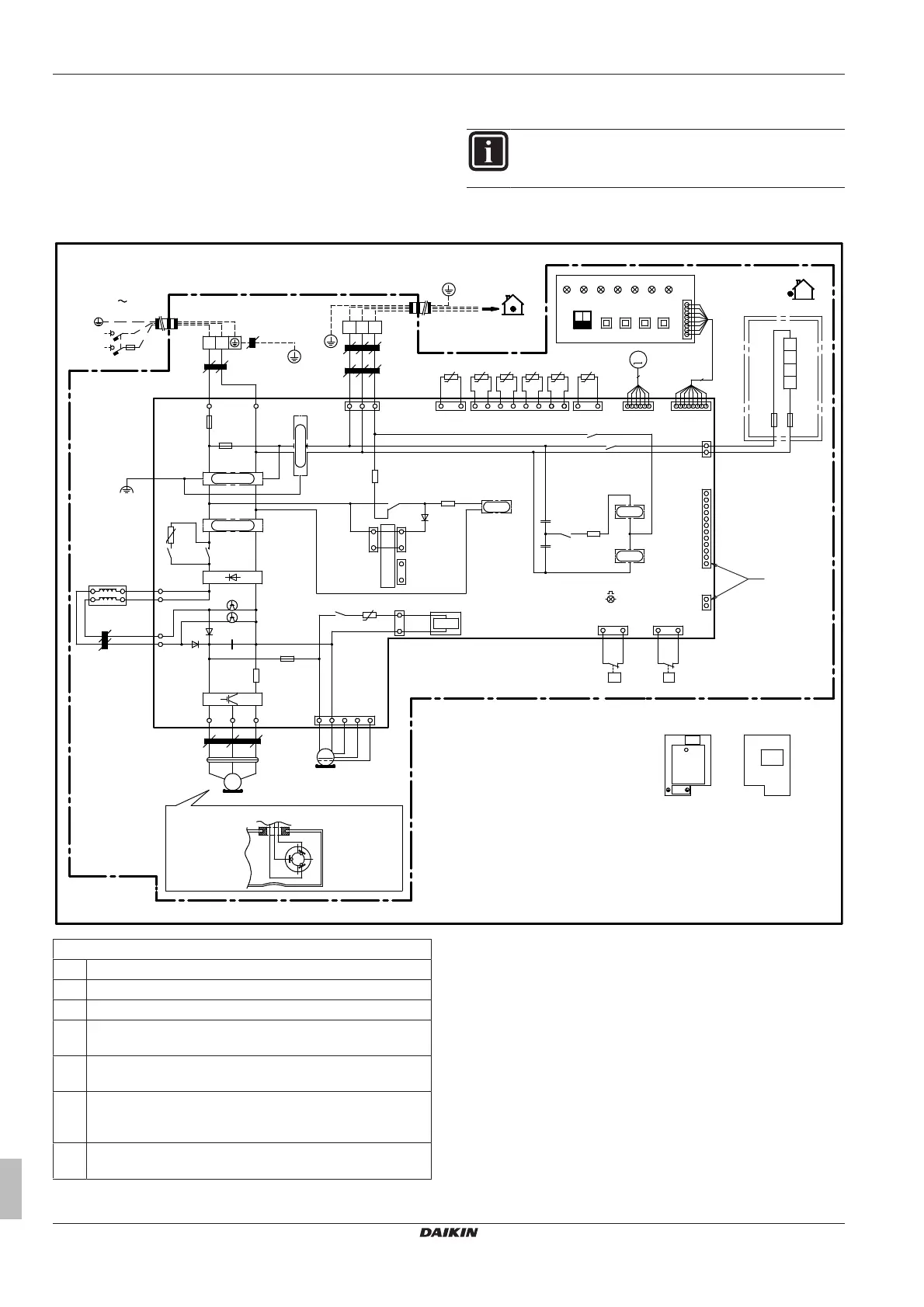
12.5 Wiringdiagram
12.5.1 Wiringdiagram:Outdoorunit
Thewiringdiagramisdeliveredwiththeunit,locatedattheinsideof
theservicecover.
INFORMATION
Foralegendexplainingthefiguresbelow,refertotheend
ofthistopic.
AZQS100_V1
R6
K15R
TC
RC
K10R
K11M
+
C1
V3D
V1T
X25A
PS
K13R
X804A
X806A
X805A
X106A
M1F
MS
HAP
H1P H3P H5P H7P
H2P H4P H6P
BS1 BS2
BS3 BS4
ON
DS1
2
1
OFF
X11A
X12A
R3T
t°
R1T
t°
X13A
R6T
t°
R2T
t°
R4T
t°
R5T
t°
M
S1PH
P>
S1PL
P<
K1R
Y1S
A2P
A1P
W
V
U
X31AX32A
X21A
Y1E
C2
C3
A1P
L1R
X1M
HAP
F8U
F7U
E1H
X6A
6
V2R
N
220-240V
1N 50Hz
L
NA
L
N
LA
RED BLU
X803A
2 31
Z3C
N=1
X1M
X1M
Q1DI
F2U
F1U
Z1F
Z3F
E1
Z2F
V2T
V2D
+ -
HR1
HR3
L1R
HR4
HR2
Z5C
N=6
V1R
W
V
RED
~
Z4C
X502A
N=4
U
WHT
V
W
U
3
MS
BLU
M1C
F6U
R2
R4
+ -
V1D
R5
+t°
R8T
X77A
X28A
X5A
8
X205A
A2P
R7T
+t°
WHT
BRN
PPL
RED
Z2C
N=3
Z6C
N=1
Z1C
N=5
BLK
WHT
RED
K14R
K2R
GRN/YLW
GRN
2D089497B
Indoor
SEE NOTE 7
Rear viewFront view
Electronic component assembly
Position of elements
Position of compressor terminal
Notes:
1 Symbols(seelegend).
2 Colours(seelegend).
3 Thiswiringdiagramappliesonlytotheoutdoorunit.
4 Refertothewiringdiagramsticker(onthebackoftheservice
cover)forhowtousetheBS1~BS4andDS1switches.
5 Whenoperating,donotshortcircuitprotectivedevicesS1PH
andS1PL.
6 Refertotheservicemanualforinstructionsonhowtosetthe
selectorswitches(DS1).Thefactorysettingofallswitchesis
OFF.
7 Refertothecombinationtableandtheoptionmanualforhow
toconnectthewiringtoX6A,X28AandX77A.