6Installation
Installerreferenceguide
14
AZQS100~140B8V1B+AZQS100~140B7Y1B
Splitsystemairconditioners
4P3855291–2014.08
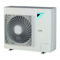
6.4.9 Todetermineifoiltrapsarerequired
Ifoilflowsbackintotheoutdoorunit'scompressor,thismightcause
liquidcompressionordeteriorationofoilreturn.Oiltrapsintherising
gaspipingcanpreventthis.
If Then
Theindoorunitisinstalled
higherthantheoutdoor
unit
Installanoiltrapevery10m(height
difference).
aRisinggaspipingwithoiltrap
bLiquidpiping
Theoutdoorunitis
installedhigherthanthe
indoorunit
OiltrapsareNOTrequired.
6.5 Checkingtherefrigerantpiping
6.5.1 Aboutcheckingtherefrigerantpiping
Theoutdoorunit'sinternalrefrigerantpipinghasbeenfactorytested
for leaks. You only have to check the outdoor unit's external
refrigerantpiping.
Beforecheckingtherefrigerantpiping
Makesuretherefrigerantpipingisconnectedbetweentheoutdoor
unitandtheindoorunit.
Typicalworkflow
Checking the refrigerant piping typically consists of the following
stages:
1 Checkingforleaksintherefrigerantpiping.
2 Performing vacuum drying to remove all moisture, air or
nitrogenfromtherefrigerantpiping.
If there is a possibility of moisture being present in the refrigerant
piping (for example, rainwater may have entered the piping), first
carryoutthe vacuumdryingprocedure below untilallmoisture has
beenremoved.
6.5.2 Precautionswhencheckingthe
refrigerantpiping
INFORMATION
Also read the precautions and requirements in the
followingchapters:
▪ Generalsafetyprecautions
▪ Preparation
NOTICE
Use a 2stage vacuum pump with a nonreturn valve that
can evacuate to a gauge pressure of −100.7 kPa (5 Torr
absolute).Makesurethepumpoildoesnotflowoppositely
intothesystemwhilethepumpisnotworking.
NOTICE
Use this vacuum pump for R410A exclusively. Using the
same pump for other refrigerants may damage the pump
andtheunit.
NOTICE
▪ Connectthe vacuumpump toboththeserviceportof
the gas stop valve and the service port of the liquid
stopvalvetoincreaseefficiency.
▪ Makesurethatthegasstopvalveandliquidstopvalve
are firmly closed before performing the leak test or
vacuumdrying.
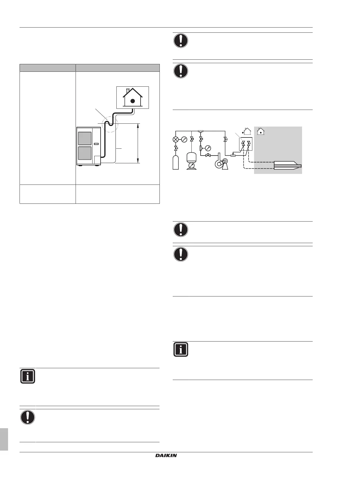
6.5.3 Checkingrefrigerantpiping:Setup
a Pressuregauge
b Nitrogen
c Refrigerant
d Weighingmachine
e Vacuumpump
f Stopvalve
6.5.4 Tocheckforleaks
NOTICE
DoNOTexceedtheunit'smaximumworkingpressure(see
"PSHigh"ontheunitnameplate).
NOTICE
Make sure to use a recommended bubble test solution
from your wholesaler. Do not use soap water, which may
causecrackingofflarenuts(soapwatermaycontainsalt,
which absorbs moisture that will freeze when the piping
gets cold), and/or lead to corrosion of flared joints (soap
water may contain ammonia which causes a corrosive
effectbetweenthebrassflarenutandthecopperflare.
1 Chargethesystemwithnitrogengasuptoagaugepressureof
at least 200 kPa (2 bar). It is recommended to pressurize to
3000kPa(30bar)inordertodetectsmallleaks.
2 Check for leaks by applying the bubble test solution to all
connections.
3 Dischargeallnitrogengas.
INFORMATION
Afteropeningthestopvalve,itispossiblethatthepressure
intherefrigerantpipingdoesNOTincrease.Thismightbe
causedbye.g.the closed state of the expansion valvein
theoutdoorunitcircuit,butdoesNOTpresentanyproblem
forcorrectoperationoftheunit.