6Installation
Installerreferenceguide
17
AZQS100~140B8V1B+AZQS100~140B7Y1B
Splitsystemairconditioners
4P3855291–2014.08
CAUTION
To avoid compressor breakdown, do NOT charge more
thanthespecifiedamountofrefrigerant.
Prerequisite:Beforechargingrefrigerant,makesuretherefrigerant
pipingisconnectedandchecked(leaktestandvacuumdrying).
1 Connecttherefrigerantcylindertoboth the service port of the
gasstopvalveandtheserviceportoftheliquidstopvalve.
2 Chargetheadditionalrefrigerantamount.
3 Openthestopvalves.
If pump down is needed in case of dismantling or relocating the
system,see"11.3Topumpdown"onpage22formoredetails.
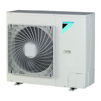
6.6.7 Tofixthefluorinatedgreenhousegases
label
1 Fillinthelabelasfollows:
a Factoryrefrigerantcharge:seeunitnameplate
b Additionalrefrigerantamountcharged
c Totalrefrigerantcharge
2 Thefilledoutlabelmustbeadheredontheinsideoftheproduct
and in the proximity of the product charging port (e.g., on the
insideoftheservicecover).
6.7 Connectingtheelectricalwiring
6.7.1 Aboutconnectingtheelectricalwiring
Typicalworkflow
Connecting the electrical wiring typically consists of the following
stages:
1 Making sure the power supply system complies with the
electricalspecificationsoftheunits.
2 Connectingtheelectricalwiringtotheoutdoorunit.
3 Connectingtheelectricalwiringtotheindoorunits.
4 Connectingthemainpowersupply.
6.7.2 Aboutelectricalcompliance
AZQS_V1+AZQS125_Y1
Equipment complying with EN/IEC 61000312 (European/
International Technical Standard setting the limits for harmonic
currents produced by equipment connected to public lowvoltage
systemswithinputcurrent>16Aand≤75Aperphase.).
AZQS140_Y1
Equipmentcomplyingwith:
▪ EN/IEC 61000312 provided that the shortcircuit power S
sc
is
greater than or equal to the minimum S
sc
value at the interface
pointbetweentheuser'ssupplyandthepublicsystem.
▪ EN/IEC 61000312 = European/International Technical
Standard setting the limits for harmonic currents produced by
equipment connected to public lowvoltage systems with input
current>16Aand≤75Aperphase.
▪ Itistheresponsibilityoftheinstalleroruseroftheequipmentto
ensure,byconsultationwiththedistributionnetworkoperatorif
necessary, that the equipment is connected only to a supply
with a shortcircuit power S
sc
greater than or equal to the
minimumS
sc
value.
Model MinimumS
sc
value
AZQS140_Y1 1170kVA
(a)
(a) Thisisthemoststringentvalue.Forspecificproductdata,
seethedatabooks.
6.7.3 Precautionswhenconnectingthe
electricalwiring
INFORMATION
Also read the precautions and requirements in the
followingchapters:
▪ Generalsafetyprecautions
▪ Preparation
DANGER:RISKOFELECTROCUTION
INFORMATION
Moreinformationaboutthelegendandthelocationofthe
wiring diagram of the unit can be found in "12.5 Wiring
diagram"onpage30.
WARNING
ALWAYSusemulticorecableforpowersupplycables.
CAUTION
For use of units in applications with temperature alarm
settings it is recommended to foresee a delay of 10
minutes for signalling the alarm in case the alarm
temperature is exceeded. The unit may stop for several
minutesduringnormaloperationfor"defrostingtheunit",or
whenin"thermostatstop"operation.
6.7.4 Guidelineswhenconnectingtheelectrical
wiring
Keepthefollowinginmind:
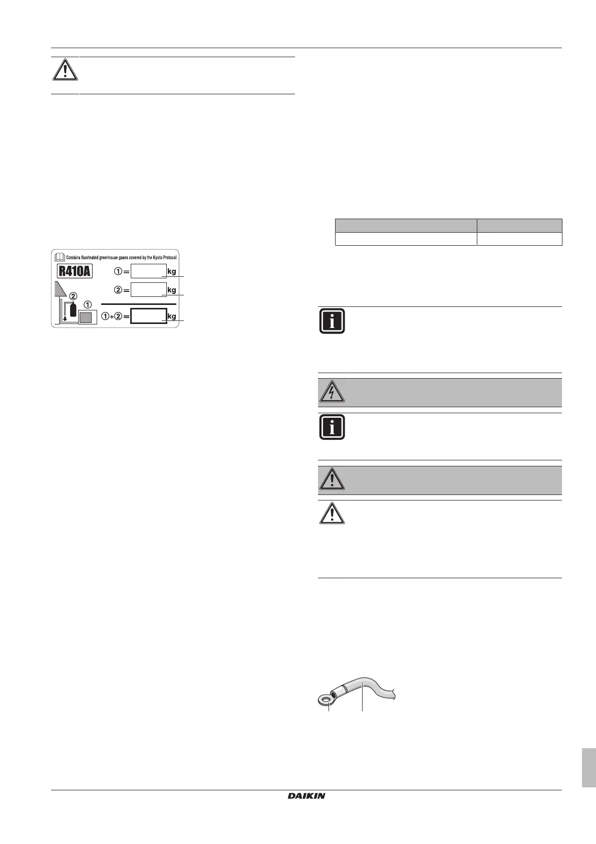
▪ Ifstrandedconductorwiresarebeingused,installaroundcrimp
style terminal on the tip. Place the round crimpstyle terminal on
the wire up to the covered part and fasten the terminal with the
appropriatetool.
a Strandedconductorwire
b Roundcrimpstyleterminal
▪ Usethefollowingmethodsforinstallingwires: