12Technicaldata
Installerreferenceguide
29
AZQS100~140B8V1B+AZQS100~140B7Y1B
Splitsystemairconditioners
4P3855291–2014.08
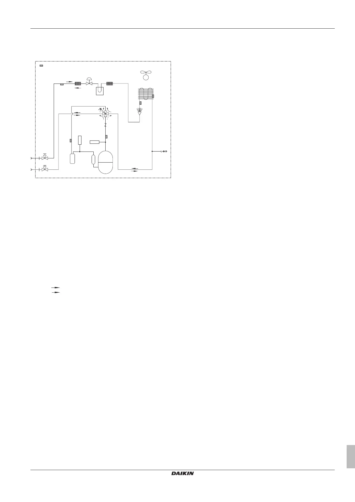
12.4 Pipingdiagram
12.4.1 Pipingdiagram:Outdoorunit
R2T
R4T
R6T
R1T
e
d
i
j
h
g
f
a
c
c
b
e
Y1E
Y1S
M1F-M2F
M1C
S1PL
S1PH
R5T
R3T
a Fieldpiping(liquid:Ø9.5flareconnection)
b Fieldpiping(gas:Ø15.9flareconnection)
c Stopvalve(withserviceport5/16")
d Accumulator
e Filter
f Heatexchanger
g Internalserviceport5/16"
h Switchboxcooling(onlyforAZQS_V1)
i Compressoraccumulator
j Checkvalve(onlyforAZQS100andAZQS125)
M1C Motor(compressor)
M1FM2F Motor(upperandlowerfan)
R1T Thermistor(air)
R2T Thermistor(discharge)
R3T Thermistor(suction)
R4T Thermistor(heatexchanger)
R5T Thermistor(heatexchangermiddle)
R6T Thermistor(liquid)
S1PH Highpressureswitch
S1PL Lowpressureswitch(onlyforAZQS_V1)
Y1E Electronicexpansionvalve
Y1S Solenoidvalve(4wayvalve)
Heating
Cooling