12Technicaldata
Installerreferenceguide
31
AZQS100~140B8V1B+AZQS100~140B7Y1B
Splitsystemairconditioners
4P3855291–2014.08
AZQS100+125_Y1
K1R
R2
K1M
L12A
L22A
L32A
L11A
L31A
L21A
F4U
F3U
F5U
F8U
F7U
X77A
X13A
R6T
R5T
F6U
GRN
Z3F
E
GRN
F2U
F1U
N=1
Z2C
N=1
Z1C
X104A
X803A
Q1DI
-
-
-
P2
P1
N=2
Z4C
+
V2R
L3AL2A
L1A
L1
L2
L1R
BRN
ORG
R3
K2R
F1U
X9A
L3L1
L2
3N~50Hz
380-415V
X108A
X8A
X111A
R10T
HAP
X4A
+
V3R
+
C1
X516A
HAP
3
2
1
A2P
+
+
C2
C3
+
R1
V1R
W
V
U
X106A
WV
U
M1C
MS
MS
M1F
N=6
Z3C
R2T
X12A
Y1E
X21A
R3TR1T
X11A
M
N
L3
N
X1M
1 2 3
X1M
R4T
NA
Z1F
Y1S
X25A
K1R
ON
OFF
1 2
DS1
BS1
X6A
PS
E1
GRN/
YLW
E1H
X28A
K2R
A1P
X1M
A
A2P
3~
X109A
Z2F
BS2
BS3
BS4
H1P
H2P
H3P
H4P
H5P
H6P
H7P
L1R
B
2D080114B
W
U
V
t°
t°
t°
t°
t°
t°
BLU
RED
WHT BLK
RED
WHT
BLK
X32A
P>
S1PH
A1P
HAP
RED
WHT
BLK
t°
N=1
Z5C
(NOTE 6)
POSITION OF
COMPRESSOR
TERMINAL
VIEW BVIEW A
EL. COMPO. ASSY FRONT
(NOTE 2)
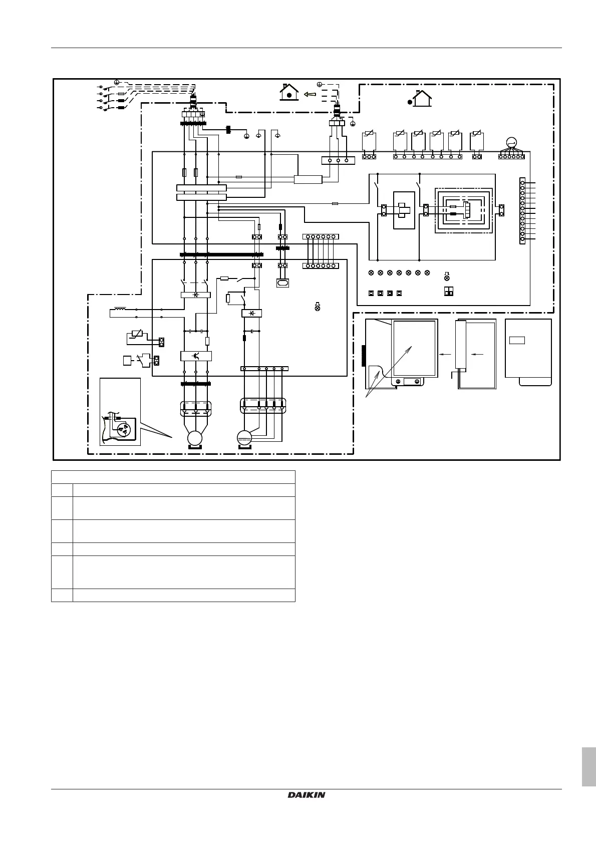
Notes:
1 Thiswiringdiagramappliesonlytotheoutdoorunit.
2 Refertothecombinationtableandtheoptionmanualforhow
toconnectthewiringtoX6A,X28AandX77A.
3 Refertothewiringdiagramsticker(onthebackoftheservice
cover)forhowtousetheBS1~BS4andDS1switches.
4 Whenoperating,donotshortcircuitprotectivedeviceS1PH.
5 Refertotheservicemanualforinstructionsonhowtosetthe
selectorswitches(DS1).Thefactorysettingofallswitchesis
OFF.
6 Onlyfor71class.