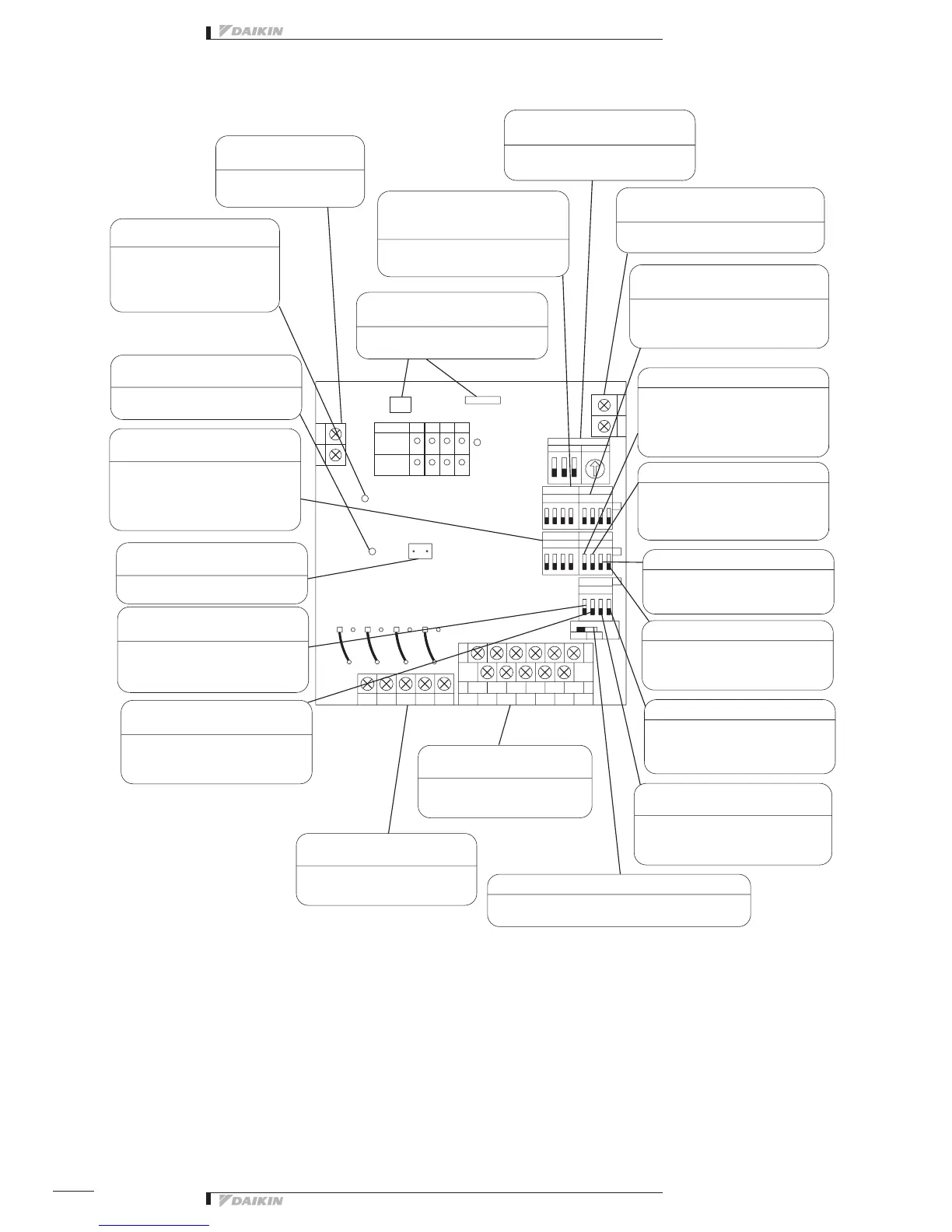
The figure below shows the PC board built in this equipment.
H4P
H12P
37268514
32184765
1423
DS6
DS2
DS3
DS4
DS5
SS1
0
D2CD D3D1 D4
CA A4
M1
A3
CM
A2A1
M4M3M2
F2
F1
N
L
H1PH2P
H3P
H10P
412
H9P
H11P
3
X1M
X2M
X3M
TNc2
HAP
TNa1
HAP
TNb4
RED
TNc1
TNa3
TNc4
GRN
TNc3
X1A
YE
TNb3
LED10
H10P
TNa4
RED
AC200V
~240V
TNb1
TP1
TNa2
X4M
TNb2
X2A
Power supply terminal block
(L, N)
Transmission error monitor
(LED10: Red)
Micro-computer OK monitor
(LED-A: Green)
Quantity change shortcircuit pin
(TP1)
Start error masks switch (DS6-1)
Error detecting switch (DS6-2)
Terminalblockforcontroloutput
(Terminal size: M3.5)
Terminalblockformonitorinput
(Terminal size: M3.5)
Output selector switch (SS1)
Monitor input switch (DS6-3)
Forced stop switch (DS6-4)
Start / Stop error switch (DS4-4)
Later push priority switch (DS4-3)
Transmission error switch (DS4-2)
Momentary stop auto switch (DS4-1)
Abnormal input detecting switch (DS2)
Terminalblockfortransmission(F1/F2)
(Terminal size: M3)
Transformerconnectingconnector
(CN1/CN2)
DIII-NET Address No. setting switch
(RS1/DS1)
Switchforselectingthenumberof
facilityequipmentconnected(DS3)
Abnormaloutputcutoff/holdswitch
(DS5)
For the power supply, use
1 ~ 200 - 240V.
When the transmission is
abnormal, the lamp lights up,
disabling remote control. (The
lamp goes out in the normal
condition.)
When the micro-computer is in
normaloperation,thelampickers.
Shortcircuit during control quantity
setting
It is possible to select whether the
erroratstartupismaskedfor10or
30 seconds.
It is possible to select whether the
equipment connection error is a non-
latch or latch error.
The start / stop signal is outputted to
the equipment to be connected
Thefacilityequipmentstatusis
monitored.
This switch makes it possible to select continuous 1
output or instantaneous 2 output.
Whether or not the abnormal condition
offacilityequipmentduringstopis
recognized can be selected.
This switch makes it possible to select
whethertheforcedstopsignalshould
befollowedorneglected.
Switchingofwhetherornoterror
detectionforstart/stopoperationfrom
i-Managerisdoneisperformed.
This switch makes it possible to select
theabsenceorpresenceoflaterpush
priority switch.
This switch makes it possible to
select whether the control output
state is maintained or not when the
transmission is abnormal.
This switch makes it possible to select
whether the system should be reset to
thestatebeforepowerfailureornot
whenthepowerfailurewasrecovered.
Whether the connected equipment
“error” is detected with contact input
“Open” or “Closed” can be selected
Connect this unit to the terminals F1, F2
ofthecentralizedcontrolequipment.
Thepowertransformerconnectoris
connected.
Alarm
Monitor
(RED)
Contact switch
Con. Ins.
ON
ON
ON
INPUT
Group No. Set
DS1 High RS1 Low
Operation
Monitor
(GRN)
Set DIII-NET Adress No.
Settheswitchaccordingtothenumberof
facilityequipmentconnections.
This switch makes it possible
to select whether the operation
output is interrupted or held when
an abnormality occurred in the
connected equipment.
 Loading...