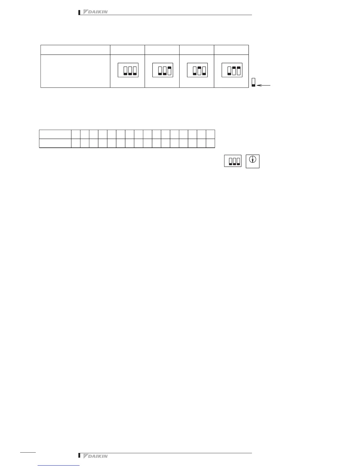
➀ SetthetopaddressofthisequipmentwiththeDIII-NETsettingswitch(DS1/RS1).UsingtheDIII-NETsettingswitch(DS1),
settherangeofAdressNo.thatissetinthisequipment.AddressNos.1-00to1-15arefactorycontrolledbeforeshipment.
∗
RS2DS1
B
11
0
00
1
01
1-00 ~ 1-15
6
06
A
10
8
08
7
07
F
15
3
03
4-00 ~ 4-152-00 ~2-15
C
12
5
05
3-00 ~ 3-15
4
04
E
14
2
02
D
13
9
09
8
*Numberofcentralizedaddressesused
Thenumberofcentralizedadressesusedisdeterminedbythetopaddresssetinthisparagraphandthenumberoffacility
equipment connected that is set in “➄ TP1 setting (Facility equipment quantity change)” paragraph.
Example1: Whenthetopaddresswassetto“1-00”andthenumberoffacilityequipmentwassetto“2”,itfollowsthat
“1-00” and “1-01” are being used.
Example2: Whenthetopaddresswassetto“3-15”andthenumberoffacilityequipmentwassetto“4”,itfollowsthat
“3-15”, “4-00”, “4-01” and “4-02” are being used.
<CAUTION>
This equipment can use the addresses between “1-00” and “4-15”.
(It is impossible to use Address 5-00 and subsequent addresses, and use any address in duplication.
Example: Whenthetopaddresswassetto“4-14”,thenumberoffacilityequipmentcannotbesetto“4”.
In this case, set it to “1” or “2”.)
➁ DS2 Setting
This switch selects whether the input is abnormal with the abnormal input contact (A1 to A4) oper or closed.
OFF(factorypresetbeforeshipment)---Abnormalintheopencondition
ON --- Abnormal in the closed condition
The relationship between each switch and abnormal input is as described below.
Input A1: DS2-1 Input A2: DS2-2
Input A3: DS2-3 Input A4: DS2-4
➂ DS4-1 Setting
Thisswitchselectsthecontroloutputstatusafterpowerfailureoccurredinthisequipmentandthepowerwasrecovered.
OFF(factorypresetbeforeshipment)---Thecontroltopowerafterpowerrecoveryishandledasstopoutput.
ON---Thecontroloutputafterpowerrecoveryishandledasoutputbeforepowerfailure.
Control range DS1 (high order)
setting (Address range)
* when a product is
dischargedfromthefactory
This indicates the
switch knob.
<Example>
When Adress No. is
set to 1-08
Address No.
indicates the
followingportionin
this case.
1-8
High
order: 1
High
order
Low
order: 8
Low
order
Set Address No. (low order) with the centralized address setting switch (RS1).
Referringtothetablebelow,settheaddressnumberloworder.
(Address Nos. are 1-00, 1-01, -- 1-15, 2-00, --- 4-15.)
Inthiscase,itfollowsthatthisequipmentusesAddressNos.
1-08 to 1-11. (4 numbers max.)
Control range DS1
Position
Address No.
RS1 Swith Setting Table
*Whenaproductisdischargedfromthefactory
ON ON ON ON
ON


 To Next Page