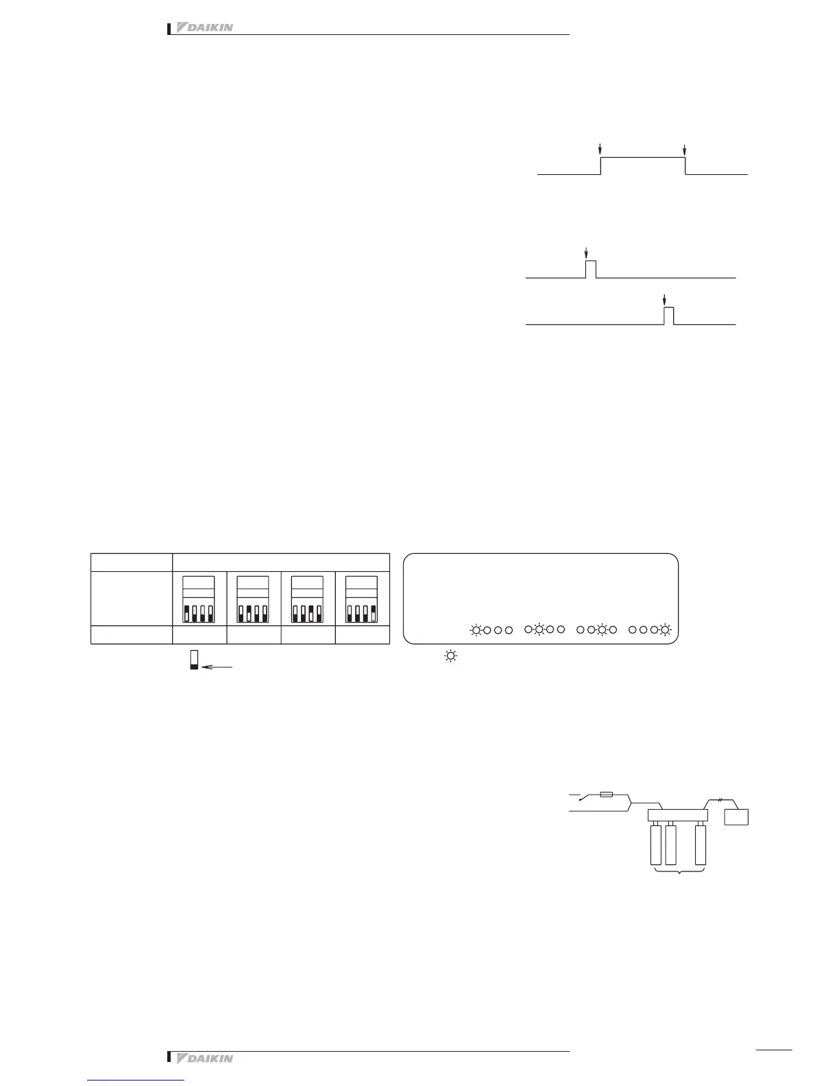
➃ DS4-1 Setting
Thisswitchselectscontinuousoutputorinstantaneousoutputforcontroloutputs(D1toD4)commandedtothefacility
equipment.Setto“Con.”side(factorypresetbeforeshipment)---Continuousoutput(ContactsD1toD4atthetimeof
operationcommandfromthecentralizedcontrolequipment:ON-ContactsD1toD4atstopcommand:OFF)
Set to “Ins.” side --- Instantaneous output
(ContactD1orD3atthetimeofoperationcommandfromthecentralizedcontrolequipment:ONforonesecondonly-Contact
D2orD4atstopcommand:ONforonesecondonly)
➄ TP1 Setting (Facility equipment quantity change)
Thisfunctionisusedtosetthenumberoffacilityequipmentcontrollablewiththisequipment.
(Thenumberofcontrollablefacilityequipmentfactorypresetbeforeshipmentis4.)
(Setting Method)
1.Turnthepower“ON”withTP1short-circuitedandchangethequantityoffacilityequipmentaccordingtotheDS3setting.
TherelationbetweenDS3settingandfacilityequipmentquantityisasperthetablebelow.
2. Turn the power “OFF”.
3. Open the TP1 and turn all DS3 switches “OFF”.
4. Turn the power ON gain.
5.Short-circuittheTP1,andchecktoseeifthesettingcoincideswiththenumberoffacilityequipmentconnectedtothis
equipment.
6. Finally, open the TP1.
*Thenumberofconnectablefacilityequipmentis4max.atcontinuousoutput,and2max.atinstantaneousoutput.
Electric wiring connection
Wiring Procedure
➀ <F1/F2> wiring between this equipment and centralized control equipment is required.
➁ Theconnectiontothefacilityequipmentandsettingofvariousswitchesarerequired.
See the “Wiring with Facility Equipment” paragraph.
➂ Connect the power supply and earth.
See the “Power Supply & Earth Wiring” paragraph.
➃ Forthewiringconnectionandclampingmethod,refertothe“WiringLead-in”
paragraph.
Wiring with Facility Equipment
<CAUTION>Thelengthofwiringbetweenthisequipmentandfacilityequipmentis100mmax.
DEC102A51
1 2 3 4
DS3 DS3 DS3 DS3
1 2 3 41 2 3 41 2 3 4
ON
OFF
Operation command
Operation command
ContactD1(1stfacilityequipment)
ContactD3(2ndfacilityequipment)
Contact D1 ~ D4
ContactD2(1stfacilityequipment)
ContactD4(2ndfacilityequipment)
Stop command
Stop command
ON
OFF
ON
OFF
TP1
1 Unit
1 Unit
Operation
Monitor
2 Units
2 Units
This indicates the switch knob.
3 Units
Switch
Power Supply
(1~200-240V)
Fuse (10A)
Centralized
control
equipment
Facility equipment
(4 numbers max.)
3 Units
By short-circuiting the quantity change TP1 in the
normal operating condition, the setting status can be
conrmed.
4 Units
4 Units
Setting Contents
Short circuit (with power “ON”)
DS3
 Loading...