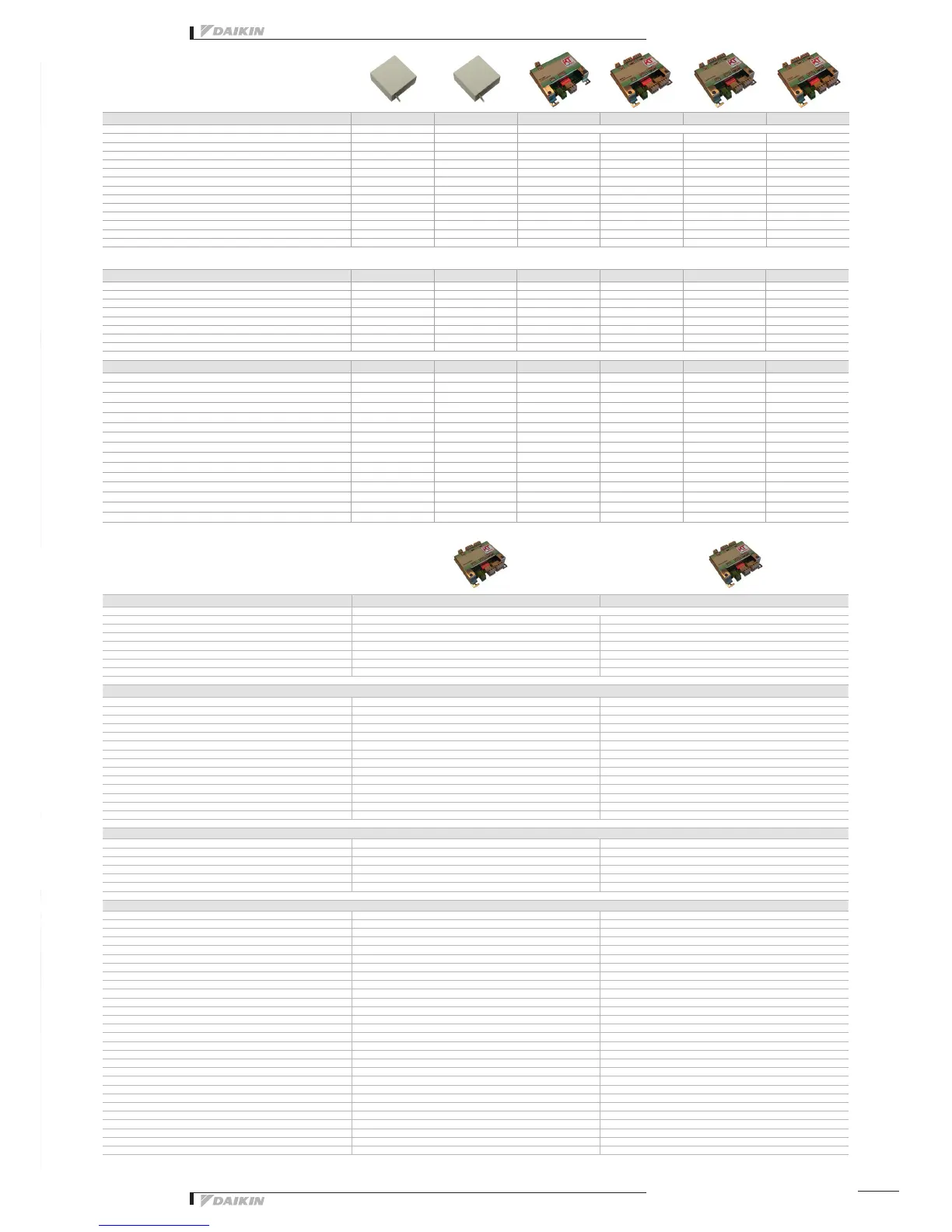
Main functions RTD-RA RTD-RA/SMART RTD-NET RTD- RTD- RTD-HO
Dimensions H x W x D mm 80 x 80 x 37,5 80 x 80 x 37,5 100 x100 x 22
Key card + window contact
Set back function
Prohibit or restrict remote control functions (setpoint limitation, ...)
**
Modbus (RS)
Group control
(1) (1)
- V control
Resistance control
IT application
Heating interlock
Output signal (on/defrost, error)
****
Retail application
Partitioned room control
Air curtain
***
***
(): By combining RTD-RA devices
Overview functions
Control functions RTD-RA RTD-RA/SMART RTD-NET RTD- RTD- RTD-HO
On/Off M,C M,C M M,V,R M M*
Set point M M M M,V,R M M*
Mode M M M M,V,R M M*
fan M M M M,V,R M M*
Louver M M M M,V,R M M*
HRV Damper control M M,V,R M
Prohibit/Restrict functions M M M M,V,R M M*
Forced thermo off M M
Monitoring functions RTD-RA RTD-RA/SMART RTD-NET RTD- RTD- RTD-HO
On/Off M M M M M M
Set point M M M M M M
Mode M M M M M M
fan M M M M M M
Louver M M M M M M
RC temperature M M M M
RC mode M M M M
nbr units M M M M
Fault M M M M M M
Fault code M M M M M M
Return air temperature (Average /Min/Max) M M M M M M
Filter alarm M M M M
Termo on M M M M M M
Defrost M M M M
Coil In/Out temperature M M M M M M
Main functions RTD-W RTD-LT/CA
Dimensions H x W x D mm
100x100x22
On/off prohibition
Modbus RS485
Dry contact control
Output signal (operation error)
Space heating / cooling operation
Domestic hot water control
Smart Grid control
Control functions
On/Off Space heating/cooling M,C M,C,V
Set point leaving water temperature (heating / cooling) M,V M,R,V
Room temperature setpoint M M
Operation mode M M
Domestic Hot water ON M,C,V
Domestic Hot Water reheat M,C M,C
Domestic Hot Water reheat setpoint M,R,V
Domestic Hot Water storage M
Domestic Hot Water Booster setpoint M
Quiet mode M,C M,C
Weather dependent setpoint enable M M
Weather dependent curve shift M M
Fault/pump info relay choice R
Control source prohibition M M
Smart grid mode control
Prohibit Space heating/cooling C
Prohibit DHW C
Prohibit Electric heaters C
Prohibit All operation C
PV available for storage C
Powerful boost C
Monitoring functions
On/Off Space heating/cooling M,C M,C
Set point leaving water temperature (H/C) M M
Room temperature setpoint M M
Operation mode M M
Domestic Hot Water reheat M M
Domestic Hot Water storage M M
Number of units in the group M M
Average leaving water temperature M
Remocon room temperature M M
Fault M,C M,C
Fault code M M
Circulation pump operation M M,C
Flow rate M
Solar pump operation M
Compressor status M M
Desinfection operation M M
Setback operation M
Defrost/ start up M M
Hot start M
Booster Heater operation M
3-Way valve status M
Pump running hours accumulated M M
Compressor running hours accumulated M
Actual leaving water temperature M M
Actual return water temperature M M
Actual DHW tank temperature (*) M M
Actual refrigerant temperature M
Actual outdoor temperature M M
M : Modbus / R : Resistance / V : Voltage / C: control * : only when room is occupied / ** : setpoint limitation / (*) if available *** : no fan speed control on the CYV air curtain / **** : run & fault


 To Next Page