Electrical wiring
Procured on-site sheathed vinyl cord
(VCTF 0.2 mm2 or 0.3 mm2)
Important
• The A (+) and B (-) terminals have polarity which must not be mixed up.
• Turn on SS1 (terminating resistance) for the adapter.
• Leave the adapter address of the circuit board to 0.
Electric wiring
The contact is constant contact. The output conditions are level reading.
• When the forced operation contact is closed, all stopped units are continuously instructed to operate.
• When the forced stop contact is closed, all operating units are continuously instructed to stop.
• Once the forced operation contact is closed, all indoor units which are stopped at that time are instructed to operate, even if the
forced stop contact is closed immediately after, the indoor units will operate for a moment and then stop. (This is the same as with
the remote control operation.)
The contact is to be purchased locally. The current applied when the contact is ON is approx. DC16V, 10mA. Input is via momentary
A-contact. Minimum 1 second is required for turning ON. Please don’t clamp with high voltage cable.
41
• Centralised control systems • DTA113B51
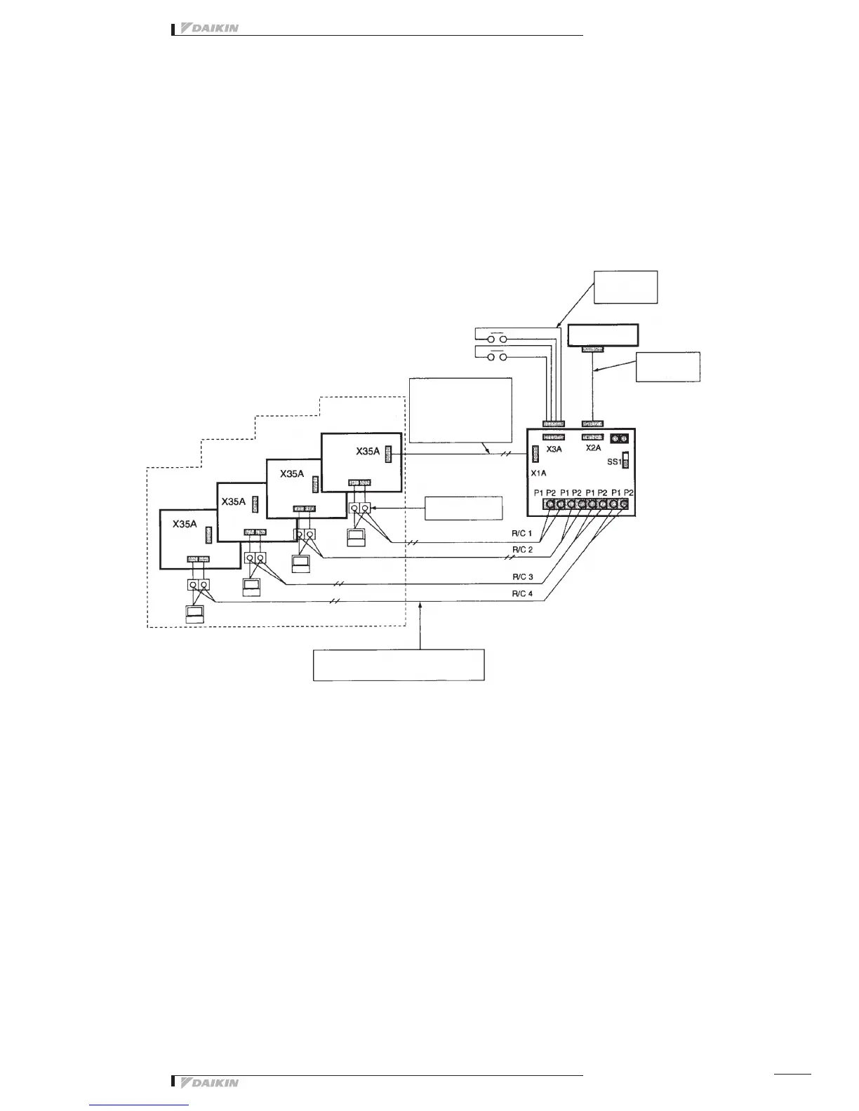
Relay harness
(3)
Relay harness
(2)
Analog Modem
Transmission wiring
terminal board (2P)
Remote control
line terminal
ON
Adapter
<DTA113B51>
Indoor PC board
connected to R/C4 on
the adapter
Indoor PC board
connected to R/C3 on
the adapter
Indoor PC board
connected to R/C2 on
the adapter
Indoor PC board
connected to R/C1 on
the adapter
This harness is to be purchased locally.
Pleaseusethesamewirehavingthesamespecicationasthewire
tobeusedforremotecontrolwiring.
Relay harness (1)
Harness to be used depends
onthemodeloftheindoorunit
to be connected.
(PleaserefertoNote1of(1).)
Forced Start input
Forced Stop input
White
Black
Red
Green
 Loading...