Wiring Diagrams ESIE05-04
1–82 Part 1 – System Outline
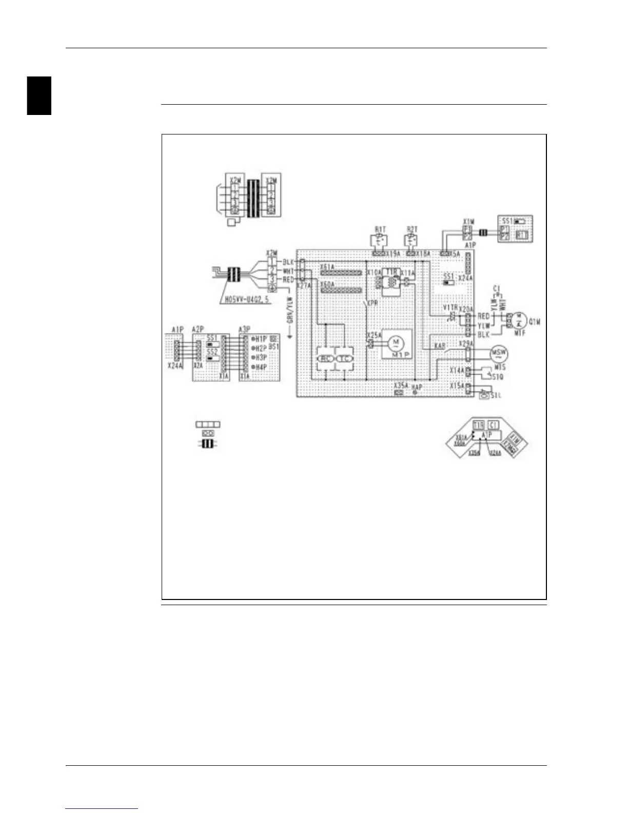
4.12 FUQ71, 100, 125B
Wiring diagram The illustration below shows the wiring diagram of the unit.
Note 4
Control box
Receiver / Display unit
In case of simultaneous operation system
Indoor unit
(Master)
Indoor unit
(Slave)
to Outdoor
Unit
Wired Remote
Controller
Remote
Controller
to Outdoor Unit
Note 4
Notes
1.
2.
3. In case using central remote controller, connect it to the unit in accordance with
the attached installation manual.
4. X24A is connected when the wireless remote controller kit is being used.
5. Remote controller model varies according to the combination system, confirm
engineering materials and catalogs, etc. before connecting.
6. Symbols show as follows:
RED : Red
BLK : Black
WHT : White
YLW : Yellow
GRN : Green
BLU : Blue
7. Confirm the method of setting the selector switch (SS1, SS2) by installation
manual and engineering materials, etc.
: Terminal
: Connector
: Field wiring
Norm.Emg.