Wiring Diagrams ESIE05-04
1–64 Part 1 – System Outline
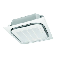
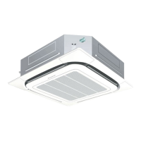
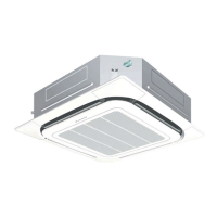
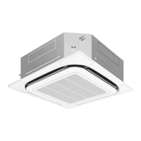
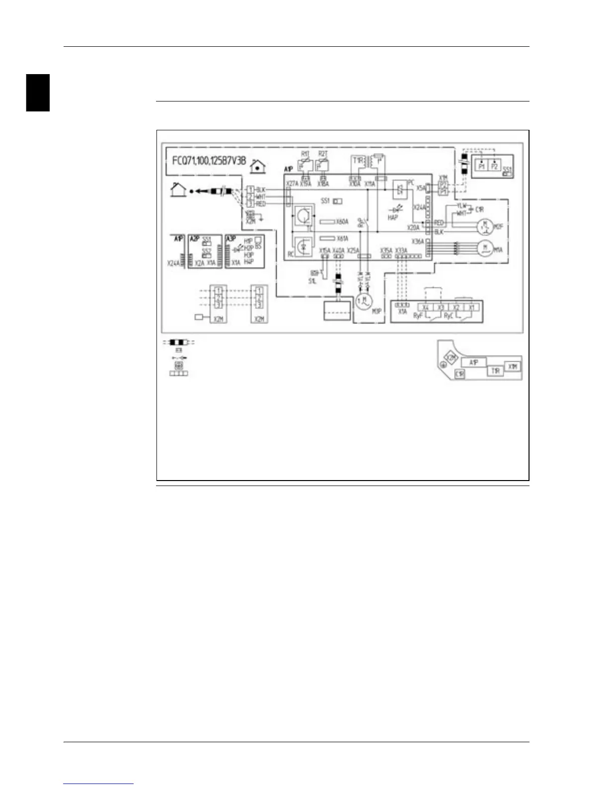
4.3 FCQ71, 100, 125B
Wiring diagram The illustration below shows the wiring diagram of the unit.
: Field wiring
: Connector
: Wire lamp
: Protective earth (screw)
: Terminal
Colors:
BLK : Black
RED : Red
WHT : White
YLW : Yellow
outdoor
indoor
Note 3
Receiver / Display unit
Simultaneous Operation System
Outdoor
unit
Remote
controller
(Master)
(Slave)
Terminals for Operation
Indicator
Fan Operation
Compressor Operation
Adaptor for
wiring
Wired Remote
Controller
Notes:
1. Use copper conductors only.
2. When using the central remote controller, see manual for connection
to the unit.
3. X24A is connected when the wireless remote controller kit is used.
4. The remote controller model varies according to the combination
system. See technical data and catalogs before connecting.
Norm.emerg.
Switch box
Remote
ON/OFF
Forced OFF