Wiring Diagrams ESIE05-04
1–74 Part 1 – System Outline
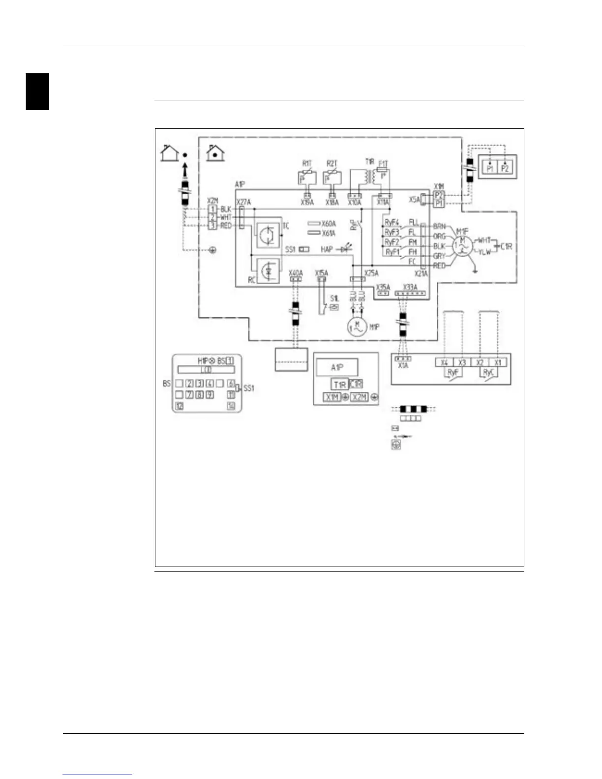
4.8 FBQ100, 125B
Wiring diagram The illustration below shows the wiring diagram of the unit.
Remote
ON/OFF
Forced OFF
: Field wiring
: Terminal
Colors:
BLK : Black
BLU : Blue
GRY : Gray
ORG : Orange
RED : Red
WHT : White
BRN : Brown
outdoor
indoor
Terminals for
Operation Indicator
Fan
Operation
Compressor
Operation
Adaptor for wiring
Wired Remote
Controller
Notes:
1. When using the central remote controller, see manual for connection
to the unit.
2. The remote controller model varies according to the combination
system. See technical materials and catalogues, etc. before
connecting.
Switch box
: Connector
: Wire lamp
: Protective earth (screw)
Details of Wired
Remote Controller
(Optional accessory)
100,125 CLASS