General Outline ESIE05-04
1–28 Part 1 – System Outline
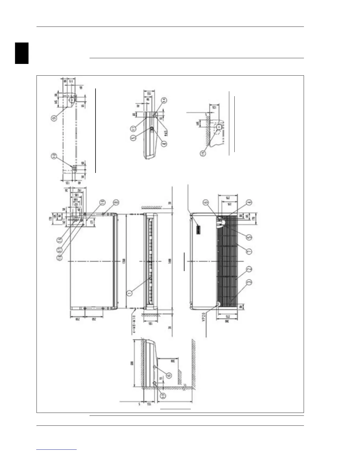
1.14 FHQ100B
Outlook and
dimensions
The illustration below shows the outlook and the dimensions of the unit (mm).
Position slit hole for taking out in piping back
or more
(Service Space)
Brand name plate
(Note 2)
Drain pipe
connection
(For left piping)
The front
Floor side
Obstacle
(Required space)
or more
For height installation
From the floor side 2500 or more
(Required space)
(View from the front)
(Hanging position)
(Hanging position)
Hanging bolt
(Required space)
or more
(Service Space)
Position of the hole in the wall for
piping straight trough the wall
(View from the front)
NOTES:
1. Location of unit’s Name plate: Bottom of fan
housing inside the suction grill.
2. In case of using wireless remote controller, this
position will be a signal receiver. Refer to the
drawing of wireless remote controller for detail.