Operating instructions
18
Daikin RoCon HP
Daikin Controller
008.1420844_13 – 02/2016
3 x Operation
3.4.8 System settings
We undertake the basic settings for the Controller RoCon HP and
the system configurations for the installation environment of the
Daikin Altherma EHS(X/H), the direct heating circuit, the hot
wa
ter generation and any optionally connected components in
the rotary switch setting "Configuration"
.
Depending on access authority (user or expe
rt), various different
parameters are available. Certain parameters are only acces-
sible to the heating expert.
LCD Display, Language, Date, Time setting
An internal pre-programmed calendar ensures auto-
matic time reset at the annually recurring
summer/w
inter time changes.
● Place the rotary switch in the "Configuration" position.
An overview is displayed.
● Select the "Setup" level with the rotary switch.
An overview is displayed.
● Se
lect the parameter [LCD Brightness] and [LCD Illum Time]
using the rotary switch and change if required.
● U
se the rotary switch to select and confirm the [Language],
[Date] or [Time] parameters.
● Select and change the value to be changed within the
individual display using the rotary switch.
● C
onfirm the changes with a brief push of the rotary switch.
Change has been accepted. Jump back to previous dis-
play.
More detailed explanations and possible setting values for this rotary switch setting
can be seen in section 3.6 and in chapter 6.2.
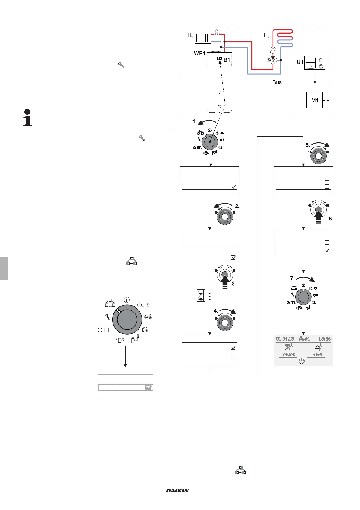
3.4.9 Terminal function
In the rotary switch setting "Remote Param" we can also
operate and parametrise other device
s integrated via the CAN
bus in the RoCon system (regulating components mixer module
or heat exchanger), provided that the individual component has
the necessary authority (see also chapter 4.3).
After activation of the "Bus -
Scan" a list of the equipment
that was recognised is shown
for selection in the display (ex-
ternal equipment and local
equipment).
After selection and confirming
an exte
rnal device, the terminal
function for this device is acti-
vated and the associated
standar
d display for this device
is shown in the display.
The operating component is
then in terminal mode.
Remote Param
Bus - Scan
No selection
Fig. 3-9 Display of the level "Re-
mote Param" at commis-
sioning or temporary
disconn
ection from the
mains
The local control element acts as the remote control for the ex-
ternal equipment. In this case a
ll the control functions are pro-
vided and saved 1:1 as on the external equipment.
The various different application and parametrisation possibilities
for using the devices and operating components combined in the
RoCon system are described in chapter 4.3.
Remote Param
Bus - Scan
No selection
Remote Param
Bus - Scan
No selection
Remote Param
No selection
Contr BM1/BE1 #X
Mix Valve #X
Remote Param
Contr BM1/BE1 #X
Mix Valve #X
Remote Param
Contr BM1/BE1 #X
Mix Valve #X
B1 Operating component RoCon B1 B1 of the
Altherma EHS(X/H)
Bus CAN-Bus (connection line bet
ween RoCon devices
and operating components)
H
1
Direct heating circuit (e.g. radiators)
H
2
Mixed heating circuit (e.g. underfloor heating)
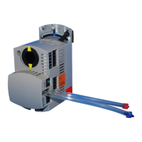
M1 Mixer module EHS157068
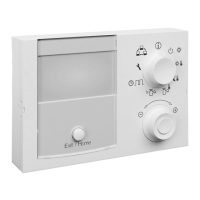
U1 Room station EHS157034
WE1 Heat generator Altherma EHS(X/H)
Fig. 3-10 Example for "Bus - Scan" on a heating system with 1 heat gen-
erator, 1 mixer, 1 room station and activation of the terminal
fu
nction for remote control of the mixer module
During this activated terminal function, the header of the display
carries additional information on the remotely controlled
equipment; the symbol
#X is displayed, where "X" indicates
the bus ID setting for the remotely controlled equipment.