6 x Parameter settings
Daikin RoCon HP
Daikin Controller
008.1420844_13 – 02/2016
Operating instructions
53
6.13.1 Rotary switch setting: Configuration , level "Setup"
Sub-
level
Parameter Description Access Setting range
Min / Max
Factory
setting
Increment
BE HF
LCD Brightness Display brightness E E 0 - 100 % 50% 10 %
LCD Illum Time Duration of display lighting E E 5 - 120 s 30 s 1 s
Language Language of the display text in the operating panel E E Deutsch
English
French
Dutch
Italian
Spanish
Portuguese
Deutsch 1
Date Current date in format day / month / year. The curren
t day of the week is calculated
automatically from the date.
E E
Time Time in format hours / minutes. E E
Keylock Function Release of the keylock function:
Off: Button block cannot be activated.
On: The button block can be activated using the rotary switch (see chapter 3.1).
E E Off
On
Off -
Access Rights Entering access code. Setting character by ch
aracter like a combination lock
(see chapter 3.6.1).
E E 0 - 9 0000 1
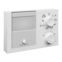
RoCon U1 assign Display only on connected
room station:
Function of the room station EHS
157034 in the CAN-data bus system:
Living Room: Control unit for the heating circuit assigned in the parameter [HC Assign-
ment] (heating circuit ID).
Mixing Valve: Mixer circuit operating unit (as
a mixer circuit extension or as a free-
standing mixer circuit controller)
In addition to the aforementioned functions, the room station can be basically used as
a remo
tely controlled unit of the Daikin Altherma EHS(X/H) and the entire RoCon sys-
tem (with activated terminal function) (see chapter 4.1 and 4.4.2).
N E Living Room,
Mixing Valve
Living Room -
PWM Config
Min Perform Pump Lower limit for modulation of the pump output N E 0 - 100 % 50% 1 %
Max Perform Pump Upper limit for modulation of the pump output N E 0 - 100 % 100% 1 %
Sensor Config
Outside Config Configuration of the outside temperature sensor:
Off: Take-over of outdoor temperature of heat generator, to which the mixer module is
al
located by the heat generator ID (Parameter [Boiler Assignment]), or no sensor eval-
uation
On: Sensor evaluation activates (if an outdoor
temperature sensor is not connected to
the EHS157068 mixer module, an error message is generated.)
N E Off
On
On -
Outside Temp Adap Individual adapting for the measured value of the outdoor temperature relevant for the
Con
troller.
N E -5.0 to +5.0 kW 0,0 K 0.1 K
Terminaladress Setting the terminal ID of the control unit for system access. The set value must be ap-
plicable for the entire system. Confirmation of
this parameter using the rotary switch
reinitialises the controller.
All settings, except "Off", empower the user of the control unit to activate the terminal
f
unction and thus to operate all RoCon system components with a valid device ID
(see chapter 3.4.9 and 4.1).
N E Off, 0 - 9 Off 1
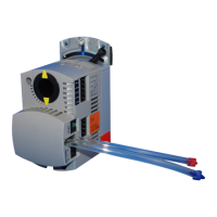
Boiler Assignment Setting the heat generator ID. Allocation of the EHS157068 to the heat generator.
The setting must correspond to the value of the parameter [BUS ID HS]
(see section 6.12, tab. 6-14).
N E 0 - 7 0 1
HC Assignment Setting the heating circuit ID of the mixer module.
Off: Automatic allocation when there is just one mixer module in the system (system
t
akes over the value of the address switch as the heating circuit ID, irrespective of the
set value). The setting must always match the heating circuit ID on the address switch
of the mixer module (see section 4.4.1, fig. 4-2).
0 - 9 = 0 - 9
10 = A
11 = B
12 = C
13 = D
14 = E
15 = F
N E Off, 0 - 15 Off 1
Tab. 6-15 Parameter in rotary switch setting "Configuration" level "Setup"