2 | Components
Service manual
95
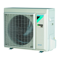
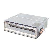
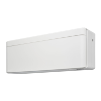
(C)(F)TXA15~50A(W)(S)(T) + (C)(F)TXA15~50B(B)(S)(T) + RXA42+50A +
RXA20~35A + RXA42+50B
Split Stylish R32
ESIE18-03C – 2020.02
3 Turn OFF the unit via the user interface.
4 Turn OFF the respective circuit breaker.
DANGER: RISK OF ELECTROCUTION
Wait for at least 10 minutes after the circuit breaker has been turned OFF, to be sure
the rectifier voltage is below 10VDC before proceeding.
5 Disconnect the DC fan motor connector S70 and measure the resistance on
the connector pins shown below. The measured resistance MUST be:
VDC Comm Resistance VDC Comm Resistance
4 1 OL 1 4 OL
4 2 108kΩ 2 4 108kΩ
4 3 1.2kΩ 3 4 1.2kΩ
4 7 OL 7 4 OL
DC fan motor resistance measurements
are correct?
Action
Yes Continue with the next step.
No Replace the DC fan motor, see "Repair
procedures"[497].
6 Turn ON the power of the unit.
7 With the DC fan motor connector S70 disconnected from the inverter PCB,
measure the voltage on the connector pins 4-7 (= fan motor power supply) on
the inverter PCB.
Result: The voltage MUST be 200~390VDC.
8 Measure the voltage on the connector pins 4-3 (= fan motor control) on the
inverter PCB.
Result: The voltage MUST be 15±10%VDC.
Is the measured voltage on the DC fan
motor connector on the inverter PCB
correct?
Action
Yes Replace the DC fan motor assembly, see
"Repair procedures"[497].
No Perform a check of the inverter PCB,
see "2.10.1Checking
procedures"[479].
To perform an electrical check of the DC fan motor assembly (fan motor rotates for a short
time)
1 First perform a functionality check of the outdoor unit fan motor assembly,
see "Checking procedures"[493].
INFORMATION
The DC fan motor connector MUST be plugged into the appropriate PCB.
2 Confirm via the service monitoring tool that the DC fan motor assembly
receives an ON signal.
 Loading...
