RC-200 Handheld Controller
7
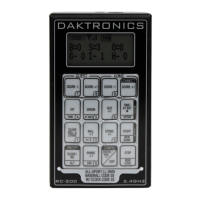
Connect Mode
Connect mode (Figure 9) is used when the wireless
handheld is connected to a wireless server Base
Station. In Connect mode, the wireless Base Station
determines the operation of the handheld, and
all operation is specic to the wireless Base Station
Function selected.
Switching to Connect Mode
After all initialization and conguration is complete, the wireless handheld controller will
be ready to connect to a wireless Base Station.
Display Action
INITIALIZING
RADIO
CONNECTING VIA
B: XX C: YY
XX = Broadcast Group #
YY = Channel #
Press <CONNECT> to create a connection to an available
wireless Base Station on the broadcast group and channel
numbers shown.
Note: The Wireless Base Station must be powered on and must
be set to the specied broadcast group and channel.
• If a connection was made, the wireless handheld will be
operating in Connect mode. Refer to the application-
specic sections for operation details.
• If a connection could not be made, refer to
Section 17:
Troubleshooting (p�36) for information about how to
resolve the problem.
Signal Strength Indicator
Once a connection has been made, the top line of the LCD
will show the signal strength (Figure 10). This indicator shows the
approximate signal strength of the network connection. Each
successive bar indicates an additional level of signal strength
between the handheld and Base Station.
When no bars or 1 bar is visible, the connection to the wireless network is likely to be
limited, and the console may occasionally fail to respond. To improve signal strength,
move within range of the Base Station, and remove any obstacles located between the
Base Station and handheld controller if possible. For more information, refer to Section 2:
RC-200 System Overview (p�4).
Figure 9: Connect Mode LCD Icon
Figure 10: Signal Strength